
Small Industry
Create automation projects with ladder logic, function blocks, structured text, and Modbus TCP.
Home automation projects can take advantage of a number of good software packages (e.g., Home Assistant and Node-RED) to manage and monitor sensors and controllable devices. If you are interested in looking at an industrial controls approach to your automation projects, then OpenPLC is a good package to consider. A programmable logic controller (PLC) is a hardened industrial hardware device that manages I/O and logic according to the IEC 61131-3 standard.
The OpenPLC open source software runs on a Raspberry Pi, Linux, or Windows PC, and it offers users a great way to learn industrial control concepts, programming languages, and communications protocols.
In this article, I introduce IEC 61131-3 programming by creating three small OpenPLC programs that use ladder logic, function blocks, and structured text programming languages. The programs in the projects presented here connect to the Raspberry Pi general purpose input/output (GPIO) pins for basic read and write functions; then, the PLC project passes data by Modbus TCP to a Node-RED dashboard.
Getting Started
The OpenPLC software comes in three packages: a logic editor, the runtime component, and a graphic builder. You can find specific instructions for your installation online. For my installation, I put the OpenPLC editor on my Ubuntu PC for some standalone configuration and testing, but you could also load both the editor and OpenPLC runtime on a Raspberry PI. The OpenPLC runtime has a web interface, so logic can be uploaded through a web browser. I didn’t install the OpenPLC graphic builder; instead, I used Node-RED dashboards as my final user interface.
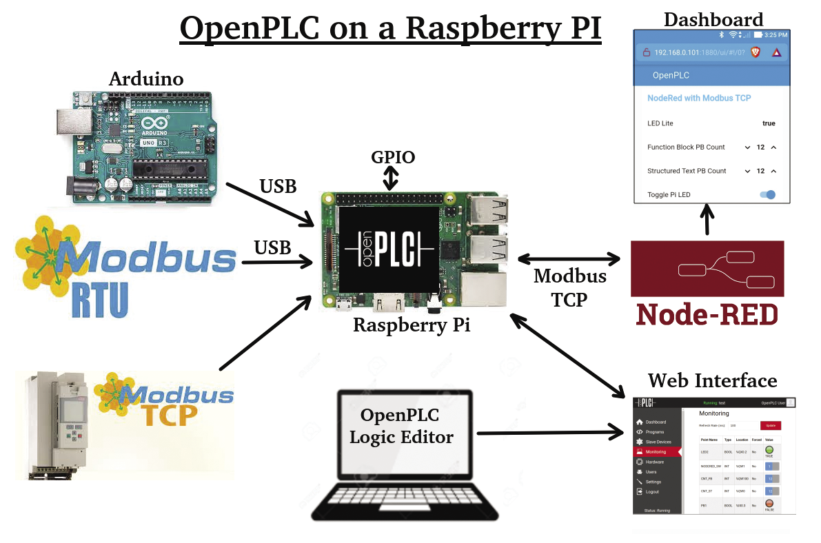
OpenPLC has a good number of optional communications packages and subsidiary I/O components (Figure 1). For this application, I created an OpenPLC project with three programs: a ladder program, a function block program, and a structured text program.
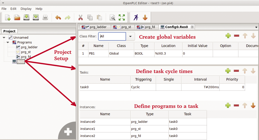
The resource object (Res0) defines global variables that can be used by all programs (e.g., pushbutton PB1) and the task cycle times (Figure 2). One of the benefits of a PLC is that it allows for easy management of task scheduling and program cycle times. Because this project is small, I put all the programs into the same task execution (task0). For a larger project, I might put all my digital logic into a fast task execution (20ms) and my analog logic into a slower task execution (250ms).
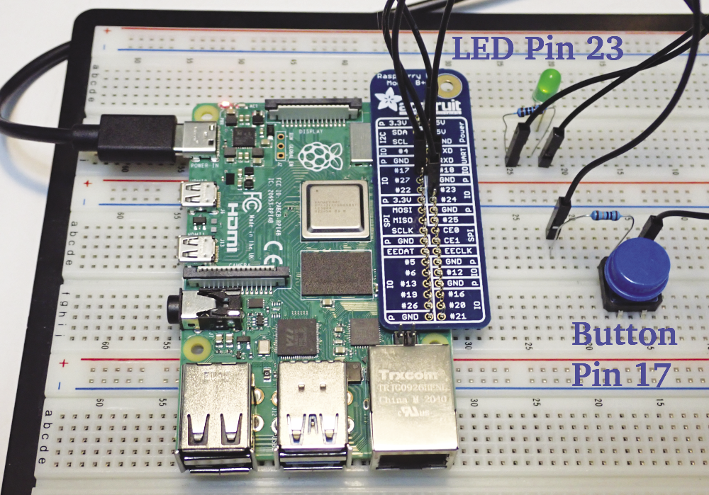
I wanted OpenPLC to do some basic Raspberry Pi pin reads and writes, so I used a setup with a pushbutton on pin 17 and an LED on pin 23 (Figure 3). OpenPLC defines the Raspberry Pi GPIO pins by IEC 61131-3 addressing (Figure 4). For this project, the pushbutton at Broadcom SOC channel (BCM) pin 17 (physical pin 11) is addressed by %IX0.3, which means an input bit on bus 0 at bit 3. The LED at BCM pin 23 (physical pin 16) is addressed by %QX0.2, an output bit on bus 0 bit 2.
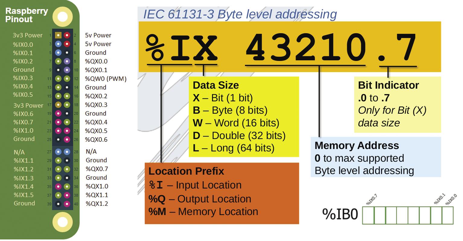
Note that OpenPLC has allocated all the left side (odd) pins of the Raspberry Pi as inputs and all the right side (even) pins as outputs.
The first step in this project is to create some IEC 61131-3 programs to connect to the Pi pushbutton and LED. Once the programs are created, they are loaded and compiled on the OpenPLC runtime; the web interface has a monitor page to view the logic variables.
Ladder Diagrams
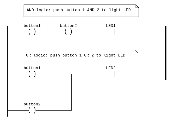
Ladder logic was the first IEC 61131-3 programming language, developed as a graphic representation for circuit diagrams of relay logic hardware. The term “ladder diagram” (LD) describes the appearance of the logic, which looks a little like a ladder (Figure 5), with the left side having a vertical power rail and the right side a vertical ground rail; a series of horizontal lines, or “rungs,” are wiring hardware components between the rails.
Most electricians feel very comfortable with ladder logic, and it is an effective programming method for managing digital logic. If you come from a programming background, ladder logic might feel a bit strange at first.
Figure 5 is an example of AND/OR logic to light two LEDs with two pushbuttons. In this example, both buttons need to be pushed to light LED 1, whereas pushing either button lights LED 2
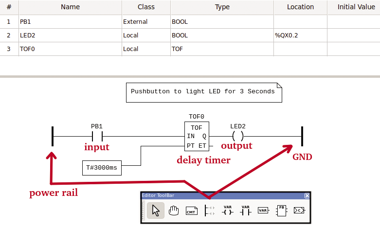
For my ladder program, I want to light an LED for three seconds with a single push of a button. In the OpenPLC editor, I referenced an external pushbutton variable, PB1 (defined in Res0), and I created two local variables: LED2, my output LED, and TOF0, an off-delay timer.
IEC 61131-3 has a wide range of functions that can be used in ladder rungs. In this example, a timer-off delay (TOF) function was inserted after the pushbutton, and the time parameter (3,000ms) is wired in as a variable (Figure 6).
Function Block Diagrams
One limitation of ladder logic is that managing analog logic can be a little messy; therefore, function block diagrams (FBDs) were developed. If you are comfortable with graphic programming applications like Node-RED, you shouldn’t have any problems working with FBDs.
For my FBD program (Figure 7) I wanted to count the number of times the LED was lit and output the value to a Modbus holding register. As in the ladder program, the external PB1 variable is referenced. A new output, CNT_FB, is defined as %QW100, an output word that can be accessed by the Modbus protocol at address 100. (I’ll explain more about Modbus when I connect Node-RED to OpenPLC.)
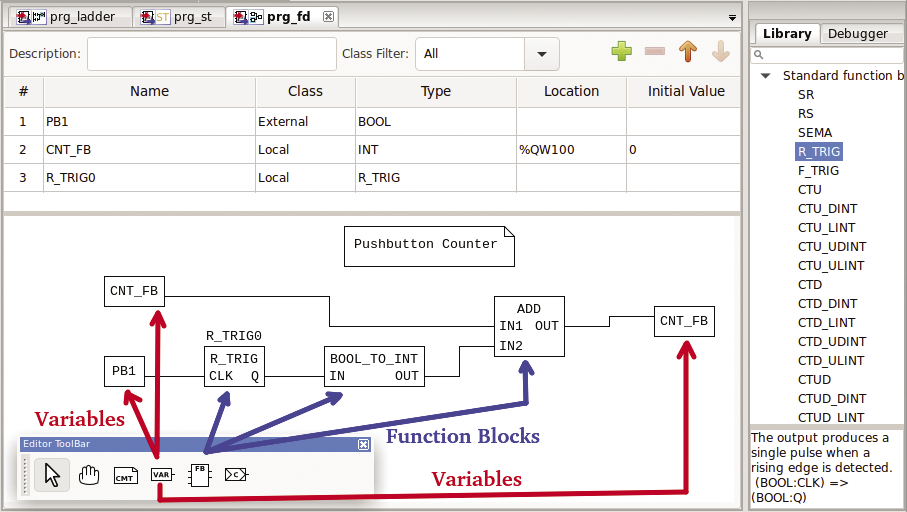
The FBD uses a rising edge trigger (R_TRIG) to catch when the LED turns on. The output from R_TRIG is a boolean, so the value is converted to an INT and added to the value of CNT_FB.
Structured Text
One of the advantages of FBDs is that they are very readable and somewhat self-documenting. The downside of FBDs is that they can be messy for complex conditional logic. Structured text (ST) was developed as a programming option that can work along with the other 61131-3 languages. Structured text is block-structured and resembles Pascal syntactically.
For my ST program, I wanted to create the same functionality as in the earlier FBD. Interestingly, the same functionality in ST took only three lines of code (Figure 8), compared with five lines in FBD. In my ST program I also added a simple IF condition to reset the pushbutton counter if the value reaches 1000.
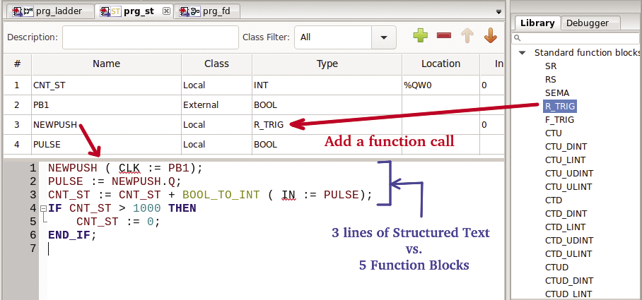
Note that library functions such as R_TRIG are available in all the 61131-3 programming languages, and you can create your own custom functions in one programming language that can be used in all the other languages.
Running OpenPLC Programs
To start the runtime application manually on the Raspberry Pi, enter:
~$ cd OpenPLC_v3
~/OpenPLC_v3$ sudo ./start_openplc.sh &
The OpenPLC runtime starts the web application on port 8080 on the Raspberry Pi.
After logging in to the web interface, the first step is to select the Hardware option and set the OpenPLC hardware layer to Raspberry Pi. Next, select the Programs option and upload the OpenPLC configuration file. After a new configuration file is uploaded and compiled, the final step is to press the Start PLC button.
For my PLC application, a button push lights the LED for 3 seconds and the function block and structured text counter variables increment up.
The Monitoring option can be used to view the status of variables in the PLC configuration. At this point, the PLC is working somewhat “headless,” so adding a Node-RED visual interface is next.
Modbus with Node-RED
Modbus [5] was the earliest and most common communication protocol used to connect industrial devices together. Modbus can be used with serial interfaces (Modbus RTU) or on Ethernet networks (Modbus TCP); both are supported by OpenPLC.
Node-RED has a number of Modbus TCP nodes that can be used. I found that node-red-contrib-modbustcp worked well for my application. New nodes can be added to Node-RED from the Manage Palette option.
A simple Node-RED application that can monitor the LED and counter statuses would use three modbustcp input nodes, a text node, and two numeric dashboard nodes (Figure 9).
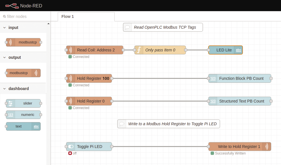
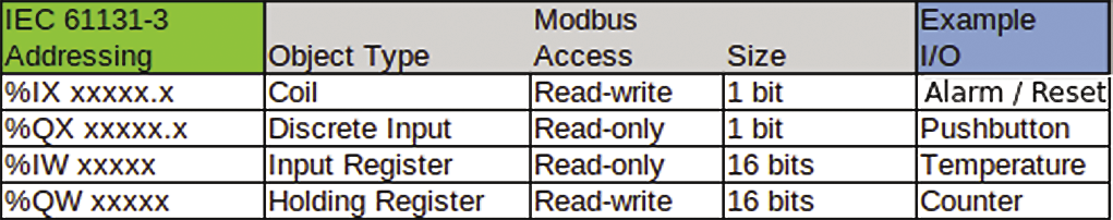
Modbus supports four object types: coils, discrete inputs, input registers, and holding registers (Figure 10). On this Node-RED application, I am only using two types of Modbus objects: a coil (a single-digit bit, LED) and holding registers (16 bits, counters). When Modbus reads a holding register, it returns just a single value (more, if requested); however, for a coil, Modbus returns 16 bits of information, not just the single bit of interest.
To show just the LED status on a Node-RED dashboard, a small function is needed (Only pass item 0) to change the message payload to just the first item in the array:
msg.payload = msg.payload[0];
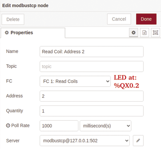
return msg;The modbustcp input node needs to be configured with the variable’s Modbus object type and address. For example , the LED’s IEC addressing is %QX0.2, which would be a coil at address 2 (Figure 11). The function block counter (CNT_FB) address, %QW100, is a holding register at address 100 (CNT_ST is a holding register at address 0).
Modbus Writes from Node-RED
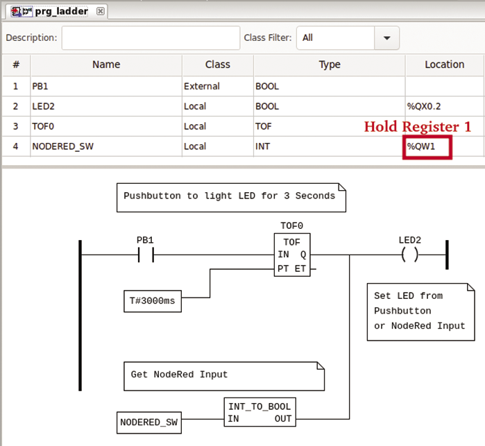
I modified the earlier ladder logic program to light the LED from either the pushbutton or a holding register (%QW1; Figure 12), which is an integer, so the value is converted to a boolean then OR’d with the pushbutton interface. The result of this OR is the value of the LED.
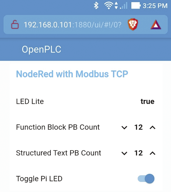
On Node-RED, a slider node is used to pass a 0 or 1 to a modbus tcp output node, which is configured as a single write to holding register 1. After the Node-RED logic is deployed, the web dashboard is accessed at: http://<your_rasp_pi>:1880/ui/ (Figure 13).
Final Comments
Learning industrial control theory can be a little challenging: It’s a very large topic with specific standards (e.g., IEC 61131-3 programming) and industry-specific communications packages like Modbus. Luckily, open source packages like OpenPLC allow you to familiarize yourself with industrial controls on low-cost hardware like the Raspberry Pi.
OpenPLC is an excellent testing and teaching tool, but it’s important to point out that OpenPLC is not designed to be used on real-time projects that have environmental or safety concerns.