Wake-up Call
In addition to enhanced performance, the Raspberry Pi 5 also comes with some new hidden functions, including options for time-controlled and remote start-up and shutdown.
In the past, restarting a shutdown Raspberry Pi was a little archaic: briefly pull out the plug and then plug it back in again. If you wanted to make things easier, you could use a cable with a built-in button or use a HAT, which was especially useful if you wanted a time-controlled reboot.
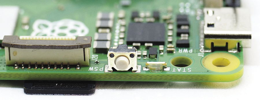
The Raspberry Pi 5 now finally has a dedicated power button (Figure 1). You can use it to start the Raspberry Pi when it’s switched off and also shut it down cleanly before it switches off the power (the operating system will even show a prompt if you’re running a desktop system). In this article, I will show you some further useful features for switching the Raspberry Pi 5 on and off.
Preparations
To make sure that everything works, you need to check a firmware (EEPROM) setting and change it if necessary. The rpi-eeprom-config command shows the configuration variables that are currently set; I’m interested in the POWER_OFF_ON_HALT entry. If it’s missing or set to 0, change it using
sudo rpi-eeprom-config --editand restart the computer. Using POWER_OFF_ON_HALT=1 ensures that the Raspberry Pi 5 only draws 3 to 4 milliamps after shutdown instead of a few hundred.
Time-Controlled Switching
Depending on what you’re using your Rasp Pi for, you may want to have it start and shutdown automatically at certain times. On many specialized systems, some script will trigger the shutdown when all current tasks have been completed and there’s nothing left to do until the next day. For example, if you have a Tvheadend-based video recorder, it lets you start a script after each recording. On my computer that script checks whether or not another recording is due shortly, and if not, it shuts down the computer. The situation is similar on my home server: It goes to sleep at 11pm sharp using a systemd timer.
Time-controlled start-up, however, is a different matter. Before the advent of the Raspberry Pi 5, it took additional HATs to automatically start a Rasp Pi. It’s great news that the latest version of the SBC has everything on board and needs no additional hardware or software. All you need to do is write the wake-up time to /sys/class/rtc/rtc0/wakealarm with sudo. Note that you need to provide the time in Unix epoch format (number of seconds since 00:00:00 UTC on January 1, 1970). That is less complicated than it sounds: the date command does the math for you. It can convert the current time or any other time to various output formats via format strings. Using +'%s', you set the format string to %s which will use the Unix epoch format. The tool also understands plain language. Figure 2 shows a few examples.
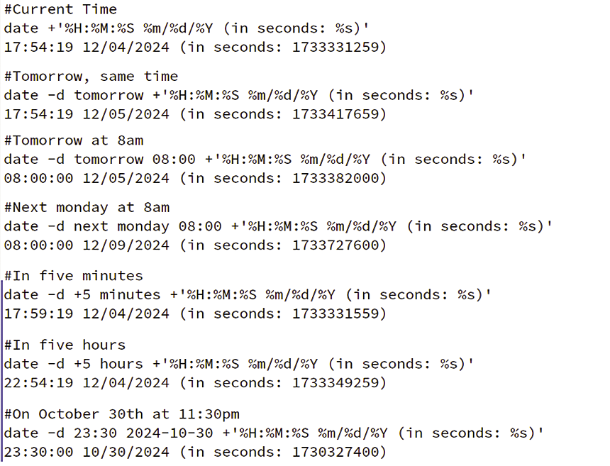
date command.Listing 1 is a small script that shuts down the computer five minutes after you’ve started it. Before shutting down, it sets the reboot time to five minutes later (10 minutes after being run). You need to run that script with sudo. The script runs the shutdown command using a relative time argument (+5), but the tool accepts absolute times, too.
Listing 1: Start/Stop via RTC
#!/bin/bash
# Next boot in ten minutes
date ‑d "+10 minutes" +'%s' > /sys/class/rtc/rtc0/wakealarm
# Check real‑time clock
cat /proc/driver/rtc
# Shutdown in 5 minutes
shutdown "+5" "Shutting down in five minutes!"
Remote Control
This procedure makes it simple to shut down the home server in the evening and then fire it up again in the morning at a fixed time. But what if you don’t always need the server at the same time? You could then simply use the remote control option. The Raspberry Pi 5 has gained an additional, unpopulated header on the board. It is located between the USB-C port and the first Micro HDMI socket (Figure 3). You will have to solder the pins shown in the figure yourself, but that is not a massive challenge.
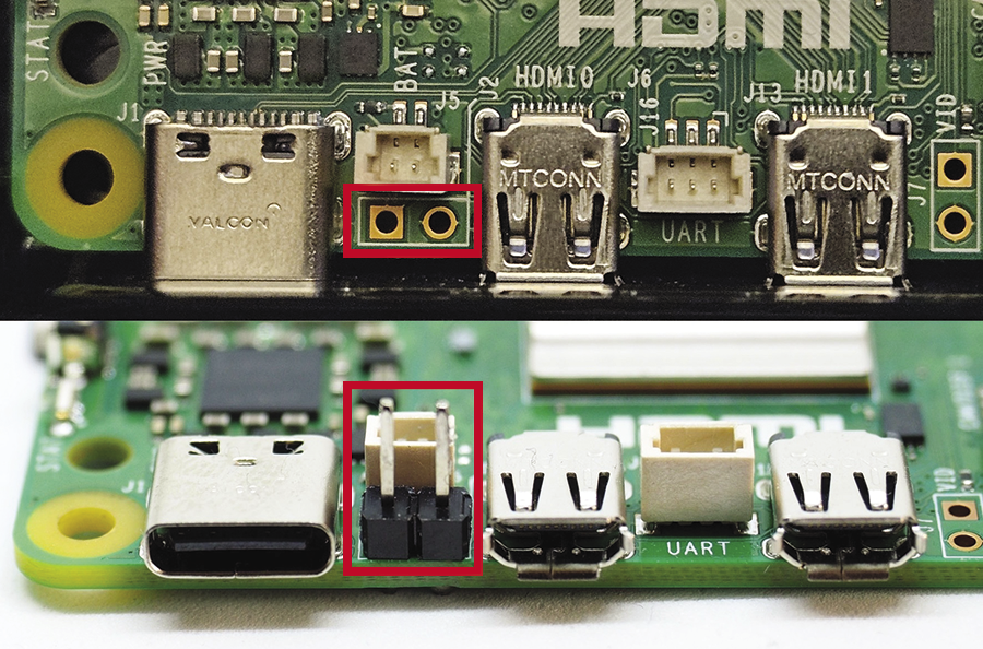
The developers probably intended this connection for positioning the button on the outside of a housing if the Raspberry Pi is completely enclosed, and it works perfectly. Instead of a button, you can connect a Pico W or some other microcontroller that’s equipped with a WLAN chip (e.g., the tiny and ancient ESP-01S is fine for this task).
The signal with a 3V3 level is on the pin directly next to the USB-C socket. Ground is the other pin (closer to the HDMI socket). You need to configure the connected Pico as an output pin in open-drain mode. The “Push-Pull and Open Drain” box explains the difference.
GPIO output pins usually support two modes (the Raspberry Pi is an exception): push-pull and open drain. In the first case, the pin actively controls the two possible values High (True, 1, positive) and Low (False, 0, negative). In the second case, it only controls Low.
The circuit shown top left in Figure 4 illustrates push-pull. Switch G1 has two states and is connected to either High or Low. An input GPIO with a pull-up is located on the right-hand side. The resistor ensures a static state when switching on as long as the output pin is not yet configured.
In an open drain configuration (Figure 4, bottom left), pin G2 only connects to Low, otherwise it is disconnected. This is not possible without a pull-up, otherwise the level at the input pin would be undefined in the latter case.
Push-pull and open drain modes are not too different for a single output pin. However, the circuit shown on the right in Figure 4 has a button in the circuit in addition to the output pin. This is the case with the Raspberry Pi 5. A push-pull output pin that is set to High and a button press then short the circuit. With open drain, either the button or the output pin can set the level to Low. You can extend the circuit with any number of open drain GPIOs and buttons.
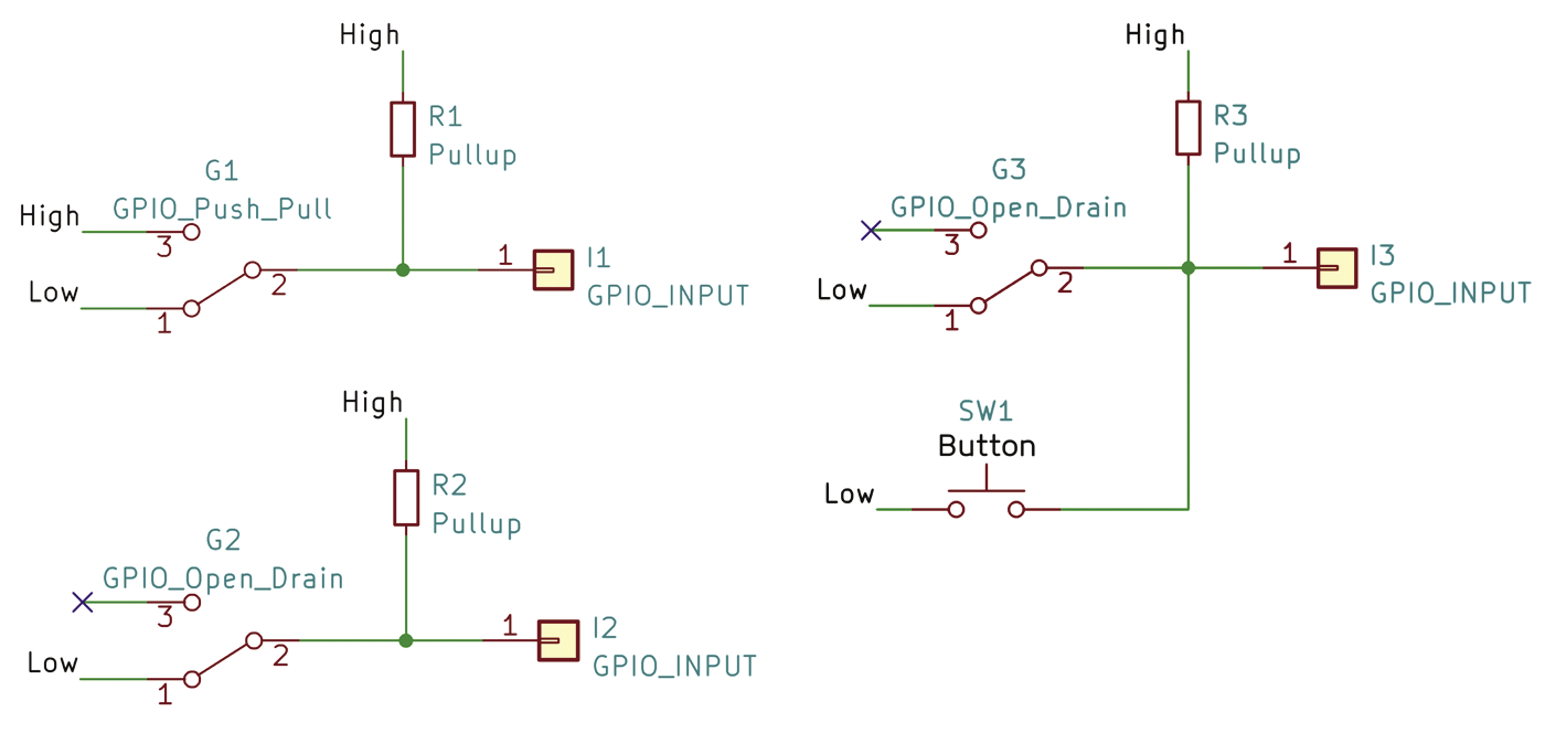
The principle is simple: One of the Raspberry Pi’s internal (input) GPIOs monitors the level at the pin. An internal pull-up also supplies the 3.3 volts (3V3) that I mentioned earlier. If a button, or in my case a Pico W, pulls the pin to ground, the Pi switches the power on or off – with the latter only happening after the system has shut down gracefully. This works because the system receives a KEY_POWER event, and it acts on it accordingly. This is the Linux standard and it should work across all distributions; laptops use the same mechanism.
Another GPIO pin on the Pico W, this time configured as an input pin, is connected to the 3V3 pin (pin 1 or 17) of the Raspberry Pi 5 via a 10K protective resistor. The Pico W uses this to check whether or not the Pi 5 is running. The entire logic is packaged in a web application that runs on the Pico W.
Mini Server
Implementing a small web server on a Pico W is not rocket science. You will find various ready-made implementations and examples for your preferred programming language online. Independently of the server function, the Pico W can log into an existing WLAN or set up its own wireless network as an access point. The latter is useful for closed or isolated environments.
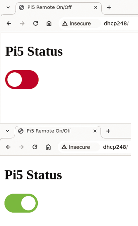
In my use case, the user interface consists of just one page – typically index.html – with a slider (Figure 5). The server delivers the file in lines 61 to 65 of Listing 2. It also provides two data interfaces: The first interface sends the current status of the Raspberry Pi 5 (Listing 2, lines 83 to 90) – that’s the value of the input pin listening on the 3V3 line. The other interface then performs the virtual button press (lines 94 to 103) by briefly pulling the output pin to ground (lines 99 to 101).
Listing 2: Web Server (Excerpt)
...
016 import board
...
024 from digitalio import DigitalInOut, Pull, DriveMode
025 from ehttpserver import Server, Response, FileResponse, route
...
041 PIN_TOGGLE = board.GP27
042 PIN_3V3    = board.GP26
043
044 class MyServer(Server):
...
050   def __init__(self):
051     self._pi5_toggle = DigitalInOut(PIN_TOGGLE)
052     self._pi5_toggle.switch_to_output(True,drive_mode=DriveMode.OPEN_DRAIN)
053     self._pi5_3v3    = DigitalInOut(PIN_3V3)
054     self._pi5_3v3.switch_to_input(pull=Pull.DOWN)
...
061   @route("/","GET")
062   def _handle_main(self,path,query_params, headers, body):
...
065     return FileResponse("/www/index.html")
...
083   @route("/get_status","GET")
084   def _handle_get_status(self,path,query_params, headers, body):
...
088     status = {"pi5_state": self._pi5_3v3.value}
089     return Response(json.dumps(status),
090            content_type="application/json")
...
094   @route("/toggle_power","GET")
095   def _handle_toggle_power(self,path,query_params, headers, body):
...
099     self._pi5_toggle.value = False
100     time.sleep(0.1)
101     self._pi5_toggle.value = True
102     return Response(json.dumps({"rc": True}),
103            content_type="application/json")
Some CSS styling ensures that the colors of the slider on the website match: green for an active Raspberry Pi, red when it is not powered, and yellow while switching – you can easily adjust the colors for users with red-green vision impairment. A few lines of JavaScript do the rest. The entire code is available from my project repository.
You can use this deliberately minimal code as a basis for your own developments. For example, the Pico W could also ping the Raspberry Pi 5 instead of just monitoring the 3V3 line. This would make it easier to distinguish between “powered up” and “booted”. You could also use a UART to connect the Pico W and the Raspberry Pi 5 and expand the management options beyond the scope of a (W)LAN.
Conclusions
You can replace the Pico W and the web server with any other microcontroller you find in your spare parts box. When it comes to communication technology, you are by no means limited to WiFi. If you connect an infrared receiver to the MCU, you can use a standard remote control for switching. If you are using a Raspberry Pi 5 as a media player in your living room, that’s an attractive solution.
From my point of view, it is precisely these inconspicuous tiny improvements to the Raspberry Pi 5, such as the RTC and switching connection, that make the single board computer even more universally usable. Massive computational power and a PCIe connection are all well and good, but only genuinely useful for data-intensive and CPU-heavy applications.


