Change internal logic from relays to an Arduino
An electronic project at a local science center was showing its age, calling for a refresh: in this case, rebuilding it almost from scratch with an Arduino instead of relays.
A museum exhibit called Buzzwire looks like outlines of two oversized hands giving you a high five (Figure 1). Each hand has a metal handle with a loop, and your goal is to move the loops up and down the hand without touching it. For an even bigger challenge, you can try to do both hands at once in the same or opposite directions. If either loop touches the hands, a buzzer and light come on and the handle vibrates.
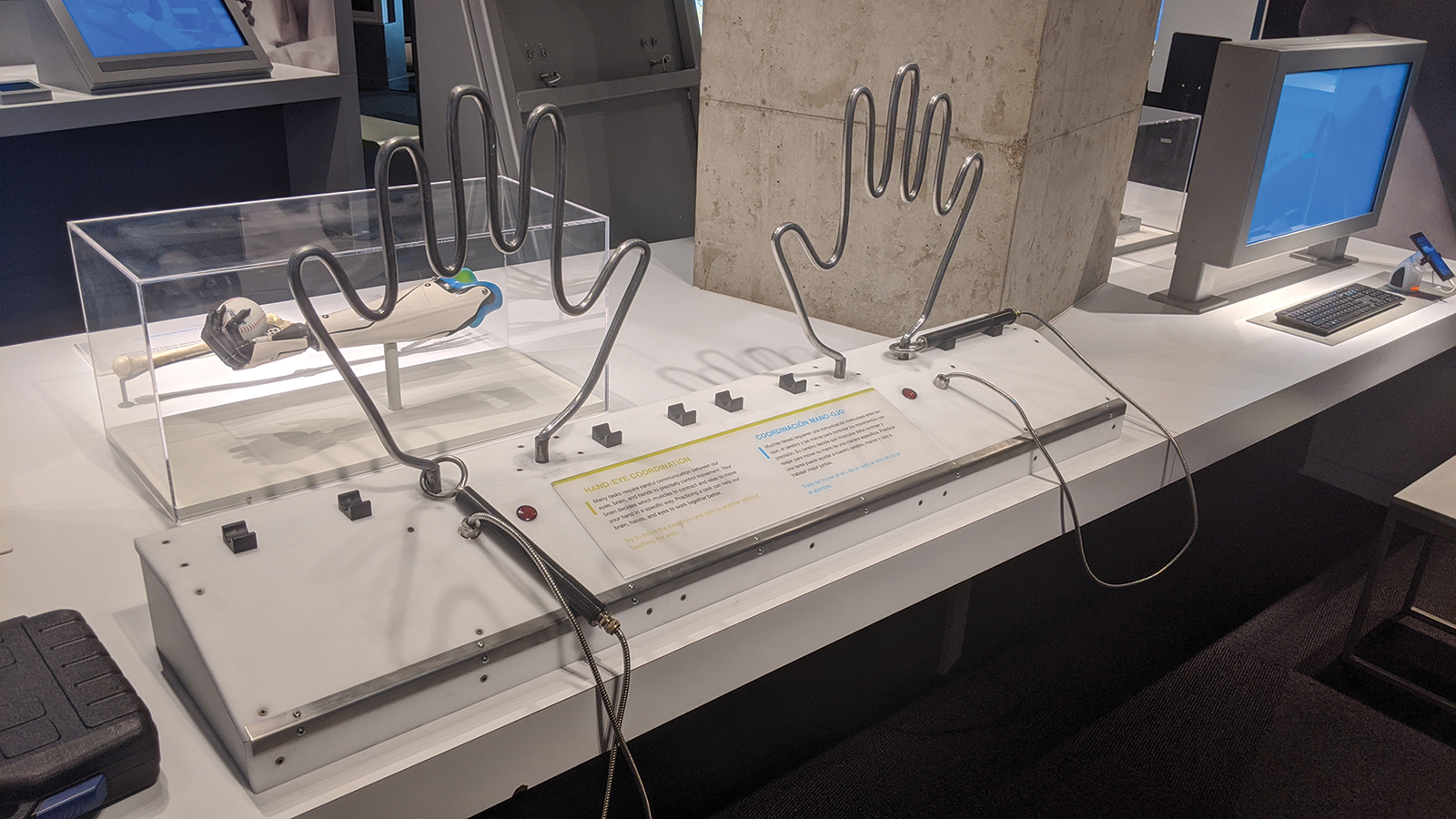
The original circuitry for the hands comprised interconnecting timer relays to switch the assorted components. The design had no microcontrollers or anything smarter than a switch, which had several drawbacks – but the main one was that if the puzzle was abandoned mid-run, the light, buzzer, and vibration motor would run continuously until the handles were removed.
Because one of the components had burned out on more than one occasion, the decision was made to rework the exhibit with upgraded technology that addresses some of its problems.
New Tech
To design the new controller, I started with an Arduino Mega because I had one on-site. An Arduino Uno would have worked just as well, but in this case, the Mega is a standard part, is easy to trade out, and is kept in stock. (See the “Physical Rebuild” box.)
While I rebuilt the control electronics, I sent the case out to be rebuilt as well. The original design was made out of plywood and had started to accumulate a lot of dings and scratches. The case rebuild was very helpful because it showed areas that needed to be reinforced. Ultimately, I had the entire front panel replaced with Delrin, a very hard plastic that will withstand wear and tear better than plywood. It also brings a fresh look for anyone that has seen it before.
The physical rebuild also incorporated larger vibration motors in the handles. The old version used pager motors, which were more heard than felt. The machine shop I worked with fabricated new handles from scratch that incorporated larger motors, making the buzz much more noticeable.
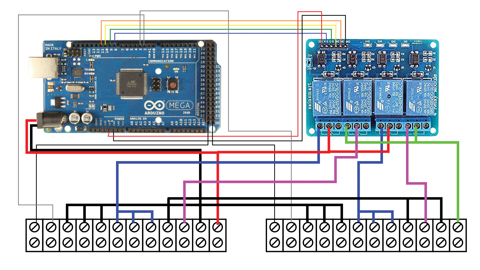
I started by assigning pins on the Arduino. The handles each need an input pin, so I started with those. Other than timers the handles are the only inputs to the circuit design. For outputs, I wanted several things to operate with different timing, so I set up four pins to control relays, which will handle both the assorted voltages and the ability to switch things on and off at different times (Table 1; Figure 2).
|
Pin |
Connection |
|
2 |
Left handle input |
|
3 |
Right handle input |
|
8 |
Relay 1 control signal |
|
9 |
Relay 2 control signal |
|
10 |
Relay 3 control signal |
|
11 |
Relay 4 control signal |
|
GND |
Left hand (puzzle) |
|
GND |
Right hand (puzzle) |
|
GND |
Relay board ground |
|
5V |
Relay board power |
Finally, for ease of connections into the exhibit itself, I assembled everything on a piece of plywood and brought all of the connections to a pair of barrier strips (Table 2). Each hand got its own barrier strip, and the two are identical except for power input on connections 11 and 12.
|
Connection No. |
Left Barrier Strip |
Right Barrier Strip |
|
1 |
Hand (sculpture) |
Hand (sculpture) |
|
2 |
Handle |
Handle |
|
3 |
Ground (1) |
Ground (1) |
|
4 |
Ground (1) |
Ground (1) |
|
5 |
Ground (1) |
Ground (1) |
|
6 |
12V (switched) (2) |
12V (switched) (2) |
|
7 |
12V (switched) (2) |
12V (switched) (2) |
|
8 |
12V (switched) (2) |
12V (switched) (2) |
|
9 |
Ground |
Ground |
|
10 |
5V (switched) |
5V (switched) |
|
11 |
Ground |
Ground |
|
12 |
12V power in |
5V power in |
|
(1) Interchangeable ground terminals. Choose one. |
||
|
(2) Interchangeable 12V terminals. Choose one. |
||
Logic Flow
Now that all of the hardware was assembled and simple test programs tested the activation of the relays, which in turn vibrated the handle or turned lights and buzzers on and off, I needed to figure out the flow of the control program.
One of the things that is often overlooked in a project is documentation. So as not to fall into that trap, I made copious notes and typed them up into a documentation package. One of the things I included was a flowchart to describe the logic (Figure 3; see the “Flowcharts” box).
Flowcharts are an excellent way to visualize flow through a system, program, or other process. In the early days of computers when programs were built on punched cards and you “programmed” on paper, they were an essential tool to understand flow. Although still useful for design, they aren’t at the forefront, as they once were. Flowcharts are seeing a resurgence, though, in online forms where data moving through a system is now visualized in the flowchart style that once originally designed it.
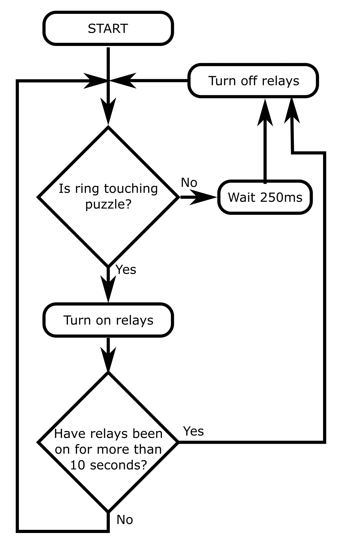
Walking through the flowchart, the first decision is the diamond right below Start asking whether the ring is touching the puzzle. If not (exit to the right), you wait 250ms, turn off the relays, and return to the original decision. It should be noted that Turn relays off will happen even if they are already off.
If the ring is touching the puzzle (exit the decision through the bottom), then turn the relays on. The next decision diamond checks whether the relays have been on for more than 10 seconds. If so (exit right), you turn off the relays and return to the first decision. If not (exit bottom), just return to the first decision.
That process will loop infinitely until power is removed from the Arduino. You should also note that this flowchart shows a simplified process. I don’t specify assigning variables or duplicating the process for both hands, just the theory of operation about what’s happening inside the logic. In this way, the program flow is easy for even a non-programmer to follow.
Code
Arduino code is made up of two sections. The setup section runs once when the Arduino powers up, and the loop section then runs infinitely until power is removed. As their names imply, they are designed to initialize everything and then run continuously.
The setup() Function
In Listing 1, lines 1-17 comprise the Arduino setup function. In this section, you tell the Arduino what you want each pin to do, set up and turn on any special functions, and define initial variables (although that’s not needed in this particular code).
Listing 1: Buzzwire
01 void setup() {
02   // put your setup code here, to run once:
03   pinMode ( 2 , INPUT_PULLUP );
04   pinMode ( 3 , INPUT_PULLUP );
05
06   pinMode ( 8 , OUTPUT );
07   pinMode ( 9 , OUTPUT );
08   pinMode ( 10 , OUTPUT );
09   pinMode ( 11 , OUTPUT );
10
11   digitalWrite ( 8, HIGH );
12   digitalWrite ( 9, HIGH );
13   digitalWrite ( 10, HIGH );
14   digitalWrite ( 11, HIGH );
15
16   Serial.begin(19200);
17 }
18
19 void loop() {
20   // put your main code here, to run repeatedly:
21   int iInput2 = 0;          // Wand 1
22   int iInput3 = 0;          // Wand 2
23   int iOut1State = 0;       // General output for Hand 1
24   int iOut2State = 0;       // General output for Hand 2
25   int iMotorReset1 = 0;     // Tracks if motor 1 has been shut off due to long contact
26   int iMotorReset2 = 0;  // Tracks if motor 2 has been shut off due to long contact
27   unsigned long ulReset1 = 0;  // Time in millis to turn off the Hand 1 buzzer and light
28   unsigned long ulReset2 = 0;  // Time in millis to tunr off the hand 2 buzzer and light
29   unsigned long ulMotor1 = 0;  // Time in millis to turn off the hand 1 motor for long contact
30   unsigned long ulMotor2 = 0;  // Time in millis to turn off the hand 2 motor for long contact
31
32   while ( 1 )
33   {
34     iInput2 = digitalRead ( 2 );  // Are we touching the hand 1 puzzle?
35     iInput3 = digitalRead ( 3 );  // Are we touching the hand 2 puzzle?
36
37     if ( iInput2 == LOW )         // If we're touching the hand 1 puzzle...
38     {
39       ulReset1 = millis() + 500; // Set a timer for 1 second from now
40       if ( ulMotor1 == 0 ) ulMotor1 = millis() + 10000;   // Set a timeout for 10 seconds from now
41       if ( iMotorReset1 == 0 ) {
42         Serial.println ( "Motor On" );
43         digitalWrite ( 8 , LOW );  // Turn on the motor if it hasn't been disabled
44         digitalWrite ( 9 , LOW );   // Turn on the light
45       }
46
47     }
48     else    // We're not touching the puzzle
49     {
50       iMotorReset1 = 0;   // Clear the timeout flag
51       //ulMotor1 = 0;       // Clear the timeout timer
52       Serial.println ( "Motor Off" );
53     }
54
55     if ( iInput3 == LOW )   // Same as above but hand 2
56     {
57       ulReset2 = millis() + 500;
58       if ( ulMotor2 == 0 ) ulMotor2 = millis() + 10000;
59       if ( iMotorReset2 == 0 ) {
60         digitalWrite ( 10 , LOW );
61         digitalWrite ( 11 , LOW );
62       }
63     }
64     else
65     {
66       iMotorReset2 = 0;
67       //ulMotor2 = 0;
68     }
69
70     if ( millis() > ulMotor1 && ulMotor1 != 0 )   // If current time (millis) is greater than the motor timeout AND we're watching for a timeout...
71     {
72       digitalWrite ( 8 , HIGH );    // Turn off the motor
73       digitalWrite ( 9 , HIGH );
74       iMotorReset1 = 1;       // Set the reset flag so we don't turn it on again
75       Serial.println ( "Motor Timeout" );
76     }
77
78     if ( millis() > ulMotor2 && ulMotor2 != 0 )
79     {
80       digitalWrite ( 10 , HIGH );
81       digitalWrite ( 11 , HIGH );
82       iMotorReset2 = 1;
83     }
84
85     if ( millis() > ulReset1 )    // Is it time to reset the buzzer / light?
86     {
87       digitalWrite ( 8 , HIGH );  // If so turn them off
88       digitalWrite ( 9 , HIGH );
89       ulMotor1 = 0;
90     }
91
92     if ( millis() > ulReset2 )
93     {
94       digitalWrite ( 10 , HIGH );
95       digitalWrite ( 11 , HIGH );
96       ulMotor2 = 0;
97     }
98   }
99 }
The pinMode functions (lines 3-9) set the Arduino input and output status. The first argument is the pin number, and the second argument is the mode. I use INPUT_PULLUP for pins 2 and 3, which are where the wires from the handles come in. A PULLUP mode tells the Arduino to turn on the pull-up resistor of a GPIO pin.
A pull-up resistor is the electronic equivalent of a default value. It uses a weak resistance to force the pin to V+. An incoming signal can literally overpower the resistor and pull it to ground. Without the pull-up resistor, electrical noise can easily make the circuit operate sporadically. Because in this case the wiring would be connected to nothing when not touching the puzzle, the pull-up setting provides a solid change of state.
Arduino pins 8-11 (lines 6-9) are set to OUTPUT. In this mode the pin will be either 5V or ground depending on its state. The digitialWrite functions in lines 11-14 set the initial states of the relays.
All states are set to HIGH to turn the relays off. Most relay modules you order online (I got mine from Amazon) operate in an inverted state. That is, a ground signal will turn them on and anything above a threshold level (usually about 1.2V) will turn them off. This setup makes them compatible with either 3.3V or 5V microcontrollers. Because the decision is either grounded or not grounded, it doesn’t matter how high the voltage goes over the threshold, as long as it is within the limits of the board.
The last line of the setup section calls Serial.begin, which turns on the built-in USB serial port on the Arduino. In this case, I’m only using it to send debug messages to the Arduino console, but for bigger projects you could also use it to communicate with a companion computer program.
The loop() Function
The rest of the program is the loop section. The first thing I do here is define a number of variables, as shown in Table 3.
|
Line No. |
Type |
Name |
Description |
|
21 |
Integer |
|
Stores |
|
22 |
Integer |
|
Stores |
|
23 |
Integer |
|
Stores whether indicators should be on for first handle |
|
24 |
Integer |
|
Stores whether indicators should be on for second handle |
|
25 |
Integer |
|
Tracks whether motor 1 has been turned off because the handle has been in contact with the puzzle too long |
|
26 |
Integer |
|
Tracks whether motor 2 has been turned off because the handle has been in contact with the puzzle too long |
|
27 |
Unsigned long |
|
Time in |
|
28 |
Unsigned long |
|
Time in |
|
29 |
Unsigned long |
|
Time in |
|
30 |
Unsigned long |
|
Time in |
The loop function cycles infinitely, but I don’t want to redefine all of my variables on every pass, so after I finish declaring my variables at the top of the section, I start another infinite (while) loop in line 32 that runs the rest of the code.
The digitalRead functions in lines 34 and 35 determine whether the handle is touching the puzzle. This state is stored in iInput2 and iInput3.
Touching the Puzzle
If the handle is touching the puzzle (i.e., the value of iInput2 in line 37 is LOW), lines 38-47 whip into action. Line 39 uses millis (see the “Electrical Noise” box) and adds 500 to get a time half a second in the future. This value is stored in ulReset1. Line 40 does the same thing for ulMotor1 if it is currently zero (not set). It also sets its time for 10 seconds (10,000ms) in the future instead of half a second.
One of the things I discovered when reworking the exhibit was that the motors that provided the handle vibration caused more electrical noise than expected. The Arduino was sensitive enough to pick up this noise as a touch, whereas the original relays did not. This new design challenge had to be overcome, and it was solved by adding a filter capacitor to each motor.
Filter capacitors can remove electrical noise that leaks back into your circuit. I described them to a coworker like this: Imagine you’re at the local amusement park and you’ve just gotten some tasty snacks while you wait in a long line for the next roller coaster. Once you eat everything you still have all of your trash. If there’s a trash can at the front of the line, you can deposit it there. Otherwise you’re trying to hold onto all of your trash while you ride the roller coaster and it flies all over the park.
Filter capacitors are like the trash cans at the front of the line. They collect the extra unwanted bits while the stuff you want (electricity) goes through. Digital electronics are much more sensitive than relay coils, and this noise problem didn’t exist in the original project, so the original designer didn’t have to consider it.
The if in line 41 checks to see whether the motor has already been shut off because the handle has been touching the puzzle for too long. If not, lines 43 and 44 use digitalWrite to turn on the relays and, by extension, the motor, light, and buzzer.
Not Touching the Puzzle
The else function block (lines 48-53) starts the counterpoint to the if on line 37. In this case, the handles are not touching the puzzle, so I clear iMotorReset1 by setting it to 0 and perform a debug print to show that the motor has been turned off.
The Long Timeout
The if block in lines 70-76 checks two conditions: Is millis (current time) greater than ulMotor1, the long timeout value, and is a timeout timer active (ulMotor1 is not equal to 0)? When the handle touches the puzzle, the delay is set for 10 seconds. If the handle remains in contact with the puzzle for that long, the motors are shut off.
The digitalWrite functions in lines 72 and 73 turn the motors off by setting the output pin to HIGH and turning off the relay. Line 74 sets the iMotorReset1 flag, and the final function sends the debug message Motor Timeout to indicate that the handle was left on the puzzle too long.
The Shorter Timeout
The simpler if block (lines 85-90) checks whether the short timer has been exceeded. Once the handle comes off the puzzle, it continues to buzz for half a second before you can continue your attempt. The digitalWrite functions in lines 87 and 88 do the work of turning the relays (and thus the motors) off; then, ulMotor1 is reset to 0 so that the buzzer can be triggered again the next time the circuit is triggered.
Conclusion
Any time you work on a project that was originally designed by someone else, you have an opportunity to learn. As you explore the existing circuitry and decide what you can reuse and what you need to replace, you discover the thought processes and electronic procedures that the previous designer incorporated into their work. This process not only gives you ideas for your next project, but also a road map for the current rebuild. Of course, if you can just talk to the original designer, the project will be much easier. As you know, that’s not always the case.
While working on this project, I incorporated a few new features, like the long timeout for when the handle is left touching the puzzle halfway through. The hope is that this change will make the handles last longer and the motors won’t burn out as quickly. I came up with a few other ideas, as well, but decided to hold those for yet another future iteration of this exhibit, which has been reinstalled on the museum floor, with guests once again enjoying getting Buzzwired.
Listing download for MakerSpace 03 2023: https://linuxnewmedia.thegood.cloud/s/XnzsiEKtagjHKr3