
Integrate hardware components with pluggable systems
Ecosystems with pluggable Raspberry Pi modules, sensors, and displays are a great choice if you don’t want to – or can’t – solder but still want to extend your hardware.
If you use your Raspberry Pi to control sensors or displays, you will frequently have to deal with wiring problems or resort to using a soldering iron. Plug-and-play systems such as Adafruit STEMMA-QT, Seeed Grove, SparkFun Qwiic, and DFRobot Gravity provide connection systems for electronic components. A system recently introduced by Tinkerforge can also be plugged together, but it plays in a different league, because it comes with an additional microcontroller for management tasks on each module.
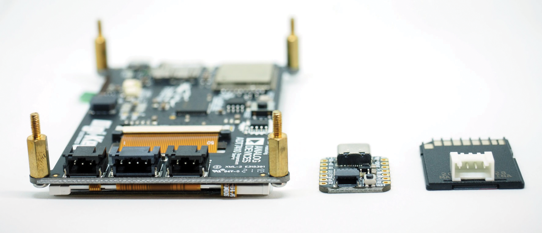
The systems I will discuss in this article offer special cable connections on the devices (Figure 1). Common to all systems are reverse-polarity-proof connectors and symmetrical cables. In other words, the cable has connectors that look identical on both sides, but they are not the same internally and only fit one way. Cables also are color coded, but this is not significant from a technical point of view.
Advantages and Disadvantages
Even though you have four manufacturers with four different pluggable systems, you do not have to make a decision and be tied to one ecosystem. However, caveat emptor still applies; I will look at the details a little later.
First, I'll look at the obvious advantages. Of great importance is the stable connection: The pluggable systems are self-locking, which is helpful not only during prototyping, but later when building solutions, as well. Even the classic jumper cables with Dupont connectors can sometimes come loose inside a housing, especially when exposed to vibrations or shocks.
The standardized connections offer another advantage. The widely used inter-integrated circuit (I2C) is standardized on the bus, but each breakout comes with its own sequence of voltage, ground, SDA, and SCL, usually because of the arrangement of the pins on the installed chip. The connector systems put an end to this setup; as a user, however, this convenience comes at the price of a larger breakout and more complicated cable routing.
Cable Only?
On closer inspection, the different systems are surprisingly compatible. The oldest system, Grove (2010), uses a proprietary four-pin connector with a pin spacing of 2mm. Adafruit’s STEMMA connectors (2014), on the other hand, rely on four- or three-pin JST-PH connectors, a widely used system. However, Japanese solderless terminals (JST, although they were developed in Germany) is not a standard. Adafruit only rarely uses the original STEMMA; sensors in particular are only available with STEMMA-QT, which I’ll get back to later.
The four-pin STEMMA connector is intended for I2C and the three-pin variant for pulse-width modulation (PWM)/analog/digital connections. The four-pin STEMMA is in principle cable-compatible with Grove thanks to an identical pin-out sequence, as well as with Gravity from DFRobot through the three-pin connection. STEMMA connectors – contrary to Adafruit’s claim – do not match up with Grove connectors. Adapter cables can be made very easily, though.
To use the right terms, the plugs are the things with pins that sit on the components, whereas the connector on the cable is a socket, although this terminology is counterintuitive and not what people actually call them; thankfully, what people mean is usually clear from the context.
The small STEMMA variant, known as STEMMA-QT (2017), uses the JST-SH connector, with a pin spacing of only 1mm. QT (cutie) is an intentional play on words. The advantage of STEMMA-QT is that it takes up less space on the breakouts, which is offset by the disadvantage that the smaller connectors cannot handle as many plugging operations. JST does not publish an exact number, but it will be somewhere in the double-digit range.
Adafruit deliberately chose the STEMMA-QT connector format to be compatible with SparkFun’s Qwiic (2017), both of which are limited to I2C only.
At the cable level, the systems from the four manufacturers form two groups: STEMMA, Grove, and Gravity use large connectors with 2mm spacing, and STEMMA-QT and Qwiic use JST-SH connectors with 1mm spacing. Adapter cables or special breakouts with matching connectors convert between the individual systems (Figure 2).
Fine Differences
Mechanical compatibility is not everything. For example, sensor and breakout components will only work with 3.3V or 5V. A normal BME280 sensor breakout (3.3V) will therefore not work on an Arduino Uno (5V) without a voltage converter; therefore, STEMMA-, Grove-, and Gravity-compatible controllers or devices come with voltage converters so that, as a user, you don’t have to worry about the voltage. Qwiic only supports the 3.3V variant, so Qwiic sensors will not work with 5V microcontrollers.
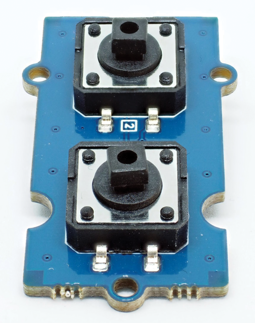
Both Grove and Gravity use the four-pin connector for more than just I2C. For example, Grove has a double push button (Figure 3) on offer, but because STEMMA only supports I2C, there is little point in plugging a button like this into a STEMMA HAT (a hardware attached on top add-on board). The same is true for Gravity devices with a universal asynchronous receiver/transmitter (UART) connection.
All in all, however, the differences between the systems are not so major that hobbyists have to commit for all time. You can pick and choose components to suit needs and availability. Many I2C components are on offer simply because of SparkFun, with its more than 150 components. Apart from I2C, however, things look a little more sparse, because Adafruit does not offer much in terms of three-pin products, and DFRobot’s Gravity components are difficult to get in Germany – which is why I chose Grove.
Application Examples
In a typical application scenario, a small-board computer (SBC) or microcontroller controls several sensors and outputs the data on a display. System providers offer suitable HATs for this purpose – or shields for the Arduino world.
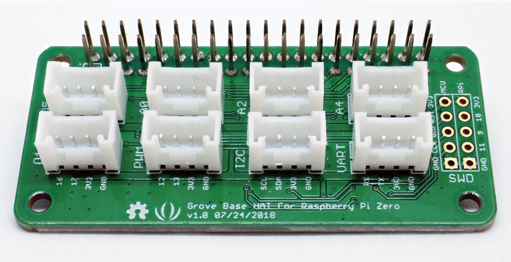
The SparkFun Qwiic HAT has four I2C connections, although your devices must be on different addresses. The Grove HAT (Figure 4), on the other hand, offers different connections – an I2C, PWM, and UART each – as well as two digital connections with two connected GPIOs each and three analog-to-digital converters (ADCs) with two channels each. The HAT has its own microcontroller for analog input and is available for $10 (~EUR10) – and in a variant with even more connections for the large Raspberry Pi models. The ADC connector alone is worth the money. For a Pico, it is best to go for the Maker Pi Pico by Cytron with its six sockets.
The double push button in Figure 3 ($2.40/EUR2.20; $2.10/EUR1.90 as a single button) is clear evidence that the plugin system is useful for solder agnostics. The cost might seem quite high at first sight, in that typical 6x6mm buttons cost just a few cents; however, the Grove push button sits on a carrier board with a socket on the back, which means you can mount it easily in a housing. As a bonus, it comes with caps in different colors. Even if DIY is not rocket science, the time you save easily justifies the price.
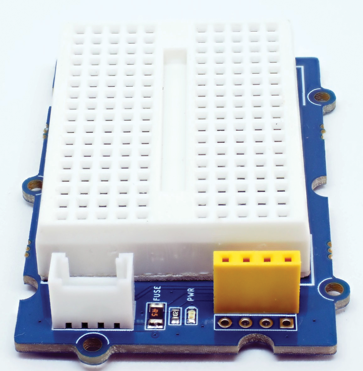
Grove tags these components as optimized for assembly with a P suffix (for “panel”). The button is also available in a version with the connector pointing upward, which is ideal for prototyping. A mini-breadboard ($3.20/EUR3) is also intended for the same purpose (Figure 5). You can use it to test your own components. A fuse (aptly labeled FUSE on the board) protects the connection.
Adapter cables with Dupont plugs or sockets at one end provide an alternative to normal breadboards. You can use them to connect Grove devices directly to a Raspberry Pi or Pi Pico, and vice versa to connect existing sensors with classic pins to a Grove HAT. The other manufacturers also offer this kind of adapter cable.
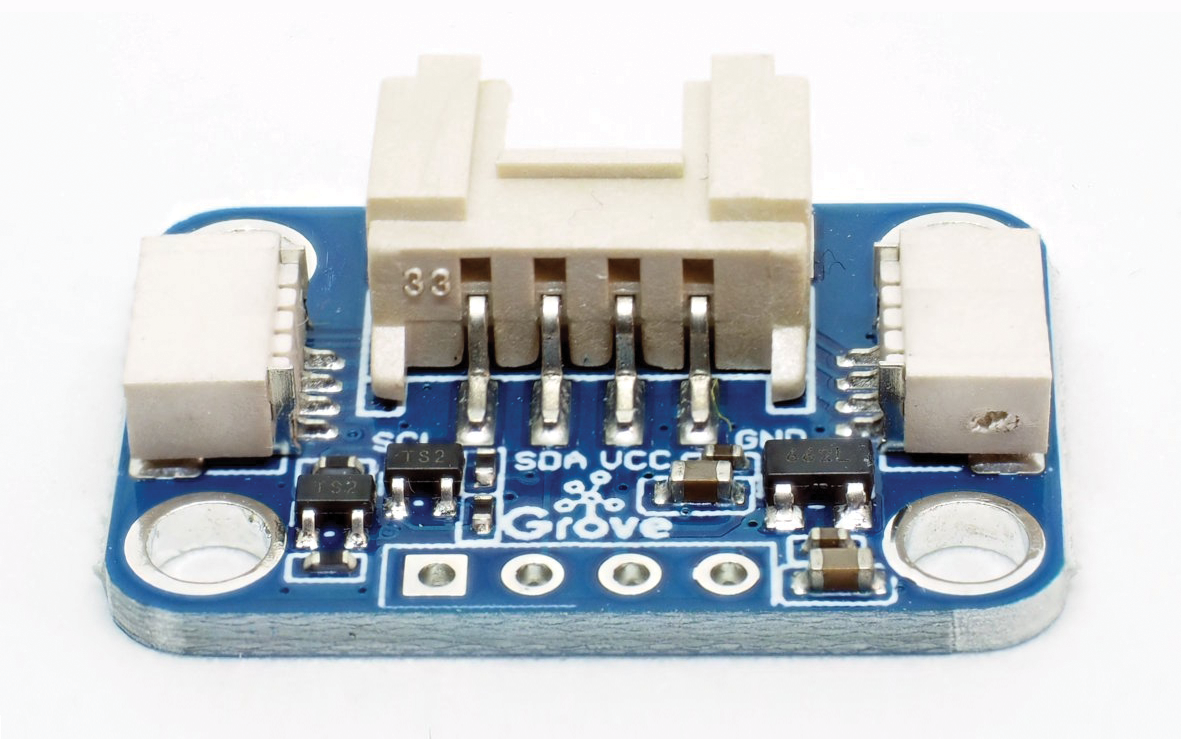
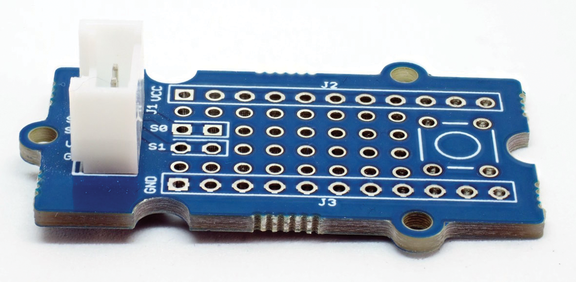
If you want your device to have a permanent Grove connection, a small proto shield (Figure 6) offers the solution ($2.10/EUR1.90). Strictly speaking, you would still need voltage converters, but for your own tinkering, you can do without them as long as you know your device’s limits.
Assembly-optimized breakouts, a mini-breadboard, and the proto shield are good arguments for the Grove system, against which other manufacturers can’t compete.
Conclusions
None of the plugin systems take the work of programming off your hands. However, you can concentrate fully on the software instead of being driven to despair by assumed programming errors that turn out to be bad connections after hours of troubleshooting. Nor do the manufacturers leave you high and dry with the programming: Each manufacturer provides wikis and sample code for its products. Seeed even gives developers a complete Python library for Grove, which gives you a standardized way to control the sensors.
If you are not a hard-core solderer or a penny-pincher, then it is definitely worthwhile investing in a cable. The system decision is more about the HAT (or the shield) than the sensors, which can be connected with an adapter cable. If you are a newcomer, Grove is the best choice. Seeed’s system offers the greatest flexibility, and the connectors are more robust than those of the smaller alternatives STEMMA-QT and Qwiic, which are restricted to I2C.