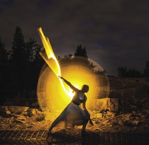
Programmable light stick with the Raspberry Pi Pico
In the photographic method of light painting, you expose a subject over an extended period of time while moving the light sources. With a little technical support from a Raspberry Pi Pico, you can achieve sophisticated results.
Without light, nothing can be seen in photography, but with just a little background light and light brushes, you can create interesting motifs. For long exposures, you need a camera with manual adjustment and a tripod. A flashlight or laser pointer is sufficient to paint simple patterns or lettering into an on-going exposure. If you like to experiment, you might want to work with LEDs to achieve particularly interesting light graphics.
I was interested in a creative approach and in trying out what can be achieved with modern pixel elements and clever programming. The idea of a light stick for light painting was born. In this article, I use a Raspberry Pi Pico to build a MicroPython programmable LED light stick.
The control does not require much in the line of interfaces, and the hardware needs to be as compact as possible – a good fit for the Pico, which is the youngest member in the Raspberry Pi family and has already seen a huge amount of interest in the last months, with some interesting HATs to match. The large community proves to be a boon if you are looking for help. Currently the smallest Raspberry Pi model, the Pico comes with an RP2040 microcontroller chip and an ARM Cortex M0+ processor, offering a state-of-the-art alternative to comparable controllers. It can run C/C++ and performs well with MicroPython.
Light Brush
In this project, I use the MicroPython firmware on the Pi Pico (Table 1). The light stick does not need a WiFi connection. For a project intended for outdoor use, it is convenient to be able to switch off the supply voltage without risking damage to an SD card. I will not be going into the details of how to get started with the Pi Pico, what you need to consider when communicating with the device, and how to program with MicroPython, because enough good articles on these subjects already exist on the web.
|
Quantity |
Item |
|
1 |
Raspberry Pi Pico |
|
2 |
LED tape WS2812b |
|
1 each |
Resistors: 460 ohm, 1.2k |
|
1 each |
Capacitor, 22nF; electrolytic capacitor, 100µF |
|
1 each |
Switch, button |
|
2 |
20-pin female connector strip |
|
1 |
Universal printed circuit board |
|
4 |
1.2V NiMH batteries (or a 5V battery pack) |
|
2 |
Aluminum U-section |
|
|
Wiring and mounting material |
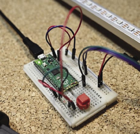
Even a small breadboard offers sufficient space to connect the essential components for some initial tests (Figure 1). The Pico has to control a multitude of RGB LEDs, and the easiest way to implement this is with NeoPixels (e.g., WS2812b), LEDs that have their own control chip and can therefore be addressed individually on the wire. Now available in many designs, they will be referred to in the following text as LEDs for the sake of simplicity.
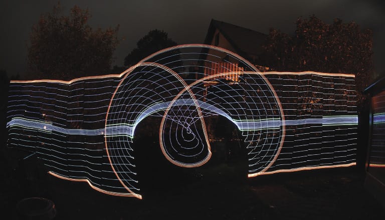
A light stick length of 2m is fine, so it can be easily transported and, above all, moved. This movement and the timed switching of certain pixels should create a satisfactory curtain of light in the finished photo (Figure 2).
Structure
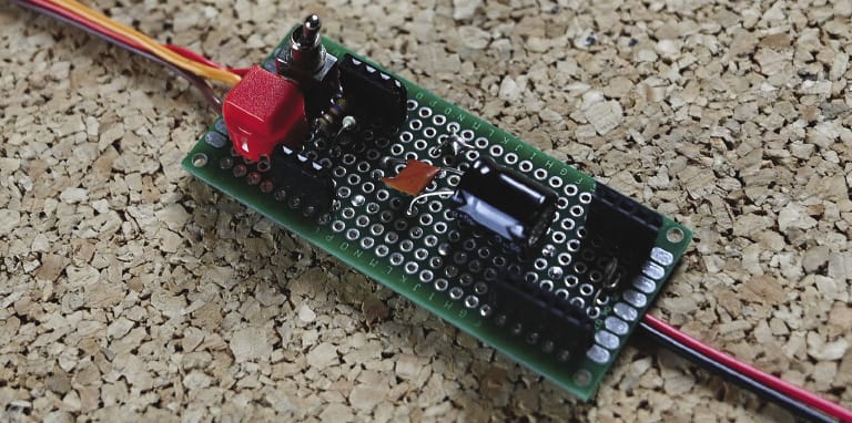
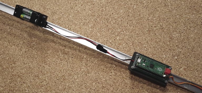
If the circuit works in the test setup, you can move on to the build. All the hardware is attached directly to the stick, which is created from a standard aluminum U-section. Luckily, the finished board turns out to be relatively compact, because with just a few components, you can work with a universal PCB (Figure 3). Ideally, the Pico will have a slot on the top side so that you can remove the PCB from the rest of the hardware. The Pi Pico is also available as an M version with soldered tips, but only a few pins have to be connected, so you can do the soldering yourself fairly quickly. That’s why the board in the figure does not have a continuous socket strip.
Because I wanted to set the light points relatively close together, I decided on a strip with 60 LEDs/m, which results in a total of 120 LEDs. The LEDs require an appropriate power supply, which cannot be taken from the Pico but must be wired directly from the source. With a circuit like this, a small serial resistor in the data line to the LED strip (at GPIO18) is a good idea. Four 1.2V NiMH batteries (micro, AAA) provide power; they can be removed and charged as needed (Figure 4). Alternatively, you could use a power bank (as small as possible) that delivers 5V. At 4.8V, the circuit still works perfectly: The LEDs reach the desired brightness and can be dimmed.
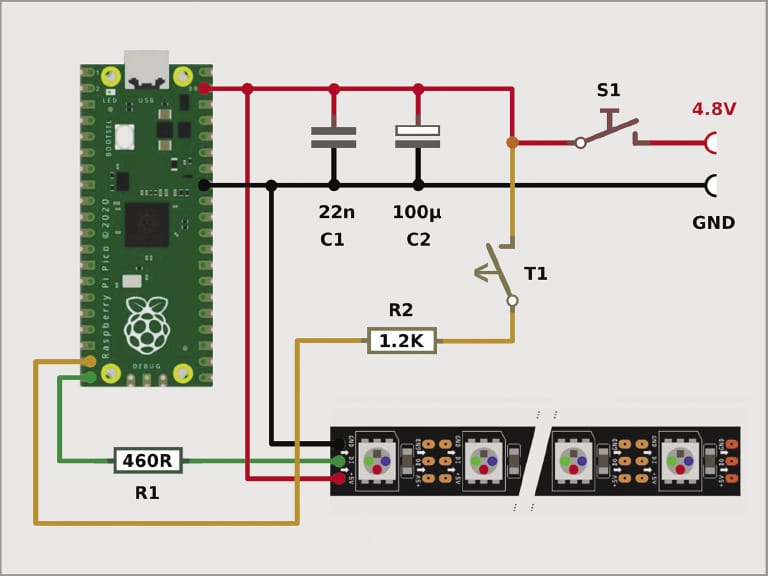
Sometimes long LED arrays will manifest errors, resulting in uncontrolled flashing of the diodes that requires stabilizing the data line and power supply. This problem did not occur with the components I used. The two capacitors in the circuit diagram (Figure 5) are provided as a precaution during alternative operation with a plug-in power supply.
Operation
In the schematic in Figure 5, you can see that T1 and R2 are connected to the GPIO17 pin of the controller. When the light stick is on, processing starts first with the pre-configured light pattern. The push button is the only control element during operation, which is necessary because the camera has to be triggered before the glow stick is used, so everything must be well timed and easy to operate. Later, I will push a button to switch to the next light pattern. The green LED on the board points backward toward the operator when shooting to provide orientation for the various flash codes.
After applying the supply voltage with a toggle switch (S1), the board LED flashes every second under software control, indicating that everything is ready. At the first button press, the flash frequency drops to two seconds, and you now have only a short time to get into recording position. Immediately before the start of the light sequence, the diode flashes very briefly, at which time you have to start moving the light stick. Everyone can create their own sequences with various levels of operating convenience.
The Pico has a control button on-board for switching to mass storage mode. If the microcontroller is connected to the computer over USB, a window with a file manager opens on Linux or Windows, and you can drag and drop source code there. A C/C++ development environment is built in, and Arduino IDE integration works, as well.
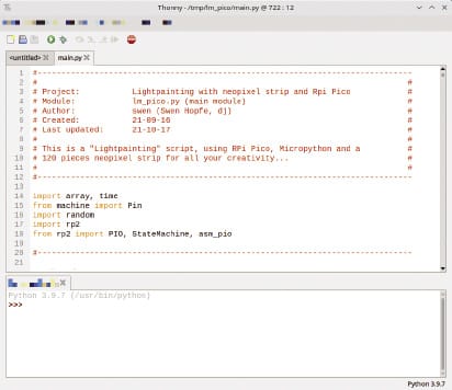
The easiest tool for Python development is Thonny. Once the lean IDE (Figure 6) has been set up for the Pi Pico and MicroPython interpreter, communication with the module is automatic. The pleasingly clear-cut editor can be configured in all of its basic features. In the Save dialog, you can choose whether to upload the source code directly to the Pico or store it in a directory, which proves to be particularly useful in practice.
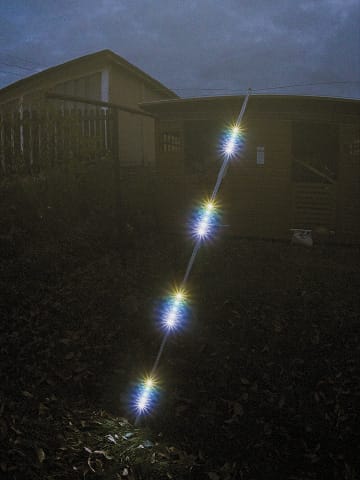
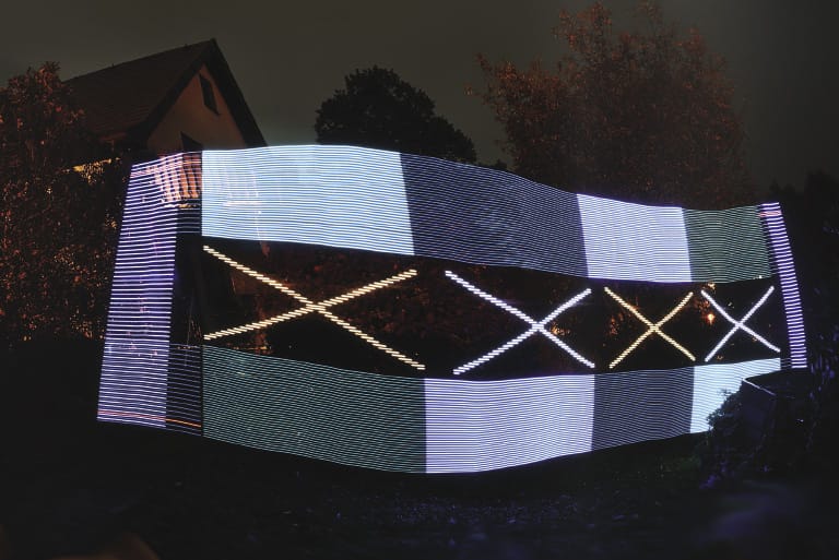
The real creativity in this project lies in the design of the sequences for the light control. The upright light stick maps the lines of the light image virtually as it moves, and you have to consider which LEDs you want to light up and at what intervals, color, and intensity so that they end up painting an interesting picture (Figure 7).
The interesting thing for the developer is that the PIO assembly and up to eight state machines can be defined in MicroPython on the Pico, so all data can be transferred fast enough to the single-wire bus that controls the LED pixels. It is a good idea to follow the documentation first and seek guidance in blogs and wikis.
After a definition block, the next part continues with some functions that update the colors of all or selected pixels – optionally in combination with a list of brightness values as used by the light control. The project source code, which can be found on my GitHub page, contains some sample methods, as well as a fair amount of information about the rest of the programming needed.
Camera Settings
For an initial shot, I went outdoors in the evening, taking care to wear dark clothing. The camera was set up on a tripod a few meters away. With a short focal length, you can capture as much of the surroundings as possible. To have sufficient time for the shot, I set the exposure time to 20 seconds at a low ISO (not greater than 800, depending on the camera). Test shots helped me determine how much of the background could be captured with a chosen aperture setting. Depending on how much ambient light you have at dusk, the aperture can be f/8.0 or smaller.
If the camera’s automatic focus doesn’t work because of the low light level, a little trick helps: Focus on a bright object nearby; if necessary, shine a flashlight on it. Once you are confident, measure the distance and adjust the focus manually. In the end, with a little improvisation, the picture can be taken without an expensive camera system.
Some interesting light sequences are prepared in the source code of the project. The animations all run for about 15 seconds, so always a bit shorter than the exposure time. When shooting, it is important to move with as steady a hand as possible. For circular shots, the light stick offers a screw connection exactly in the middle. You can change everything, with nothing to limit your creativity (Figure 8). Compared with a static illuminated object, wherein only the same traces and patterns can be seen in the same image, this project shows its strengths. As far as favorable brightness and the timed sequence of LEDs are concerned, a targeted adjustment succeeds after only a few tests.
Conclusions
The Raspberry Pi light stick project has certainly not made me a light painting expert. Far more spectacular shots can be found online. However, combining my own interest in the Raspberry Pi and in photography gave me a lot of pleasure, and I still have a lot of fun designing new light images. Results from the Pi Pico toolset and MicroPython are completely satisfactory.

