
Snake Senses
Adding Python to your Node-RED arsenal lets you create easy Raspberry Pi robotic and IoT projects.
If you want to build some fun Pi projects but are still working on your Python skills, then mixing low-code Node-RED with Python might be an option for you. Node-RED is a low-code drag-and-drop interface that is extremely powerful for the creation of Raspberry Pi robotic and Internet of Things (IoT) projects.
Node-RED’s custom scripting is JavaScript; however, you can also use Python, which offers a platform to play and learn Python basics for high-level tasks such as scheduling and web dashboards while taking advantage of Node-RED’s low-code interface.
In many cases, Raspberry Pi features are only available in Python, so even die-hard Node-RED users could benefit from knowing how to integrate Python into their projects. In this article, I look at two examples that mix Python and Node-RED. The first creates a web dashboard to drive a Raspberry Pi rover; the entire project only requires two Node-RED widgets. The second project creates an IoT page that shows temperature and humidity data from a BME280 sensor.
Getting Started
Depending on your Raspberry Pi image, Node-RED may already be installed. If not, see the Node-RED documentation or your Pi image for custom installation directions.
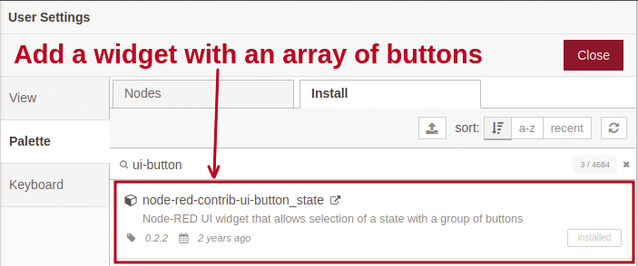
Some excellent dashboard components can be used to create lightweight web interfaces. A great widget to include in your toolset is the Button State flow for creating an array of buttons. To install this component select the Node-RED Menu | Manage Palette item, click the Install tab, and search for ui-button (Figure 1).
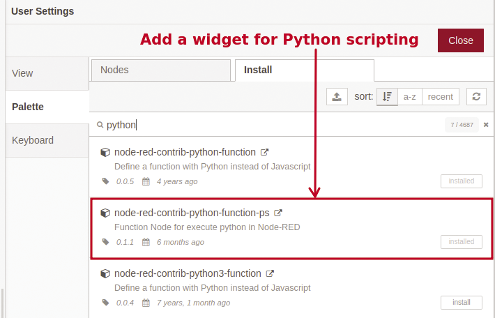
The next important step is to add a Python-enabled widget. Among the various choices, I chose the python-function-ps component (Figure 2) because it was recently updated; however, the other choices worked on my test projects, as well. The ability to use Python instead of JavaScript in Node-RED is an extremely useful feature; however, it’s not bulletproof, so some care may be needed when you’re using advanced Python libraries. In the next section, I use these two widgets to control a Raspberry Pi rover.
Raspberry Pi Rover
Many approaches that use a Raspberry Pi can lead to a car or rover. For this project I used:
• A two-motor car chassis (~$15)
• A portable battery (5V, 3A output, ~$30)
• A Raspberry Pi with a motor shield
• Four alligator clips and four jumper wires
• Elastic bands and duct tape
For this project I wanted to ensure that Python scripting with Node-RED could be used on a variety of Pi models. I tested on a 1 B+, 3, and 4. The PI 1/2 are old and slow but they have the advantage of lower power. For a Raspberry Pi 3 and 4, the portable battery needs to output 3A. If you are using a Pi 1 or 2 you can use a standard 2.1A phone charger.
Because of the power draw, connecting motors directly to a Raspberry Pi is not recommended; luckily, some good motor or automation shields are available for around $25. If you’re feeling adventurous, you can build your own motor shield with a L293D chip (16-pin motor driver integrated circuit) for about $4. On this project, I used an older PiFace Digital module, which has good Python support but weak Node-RED functionality.
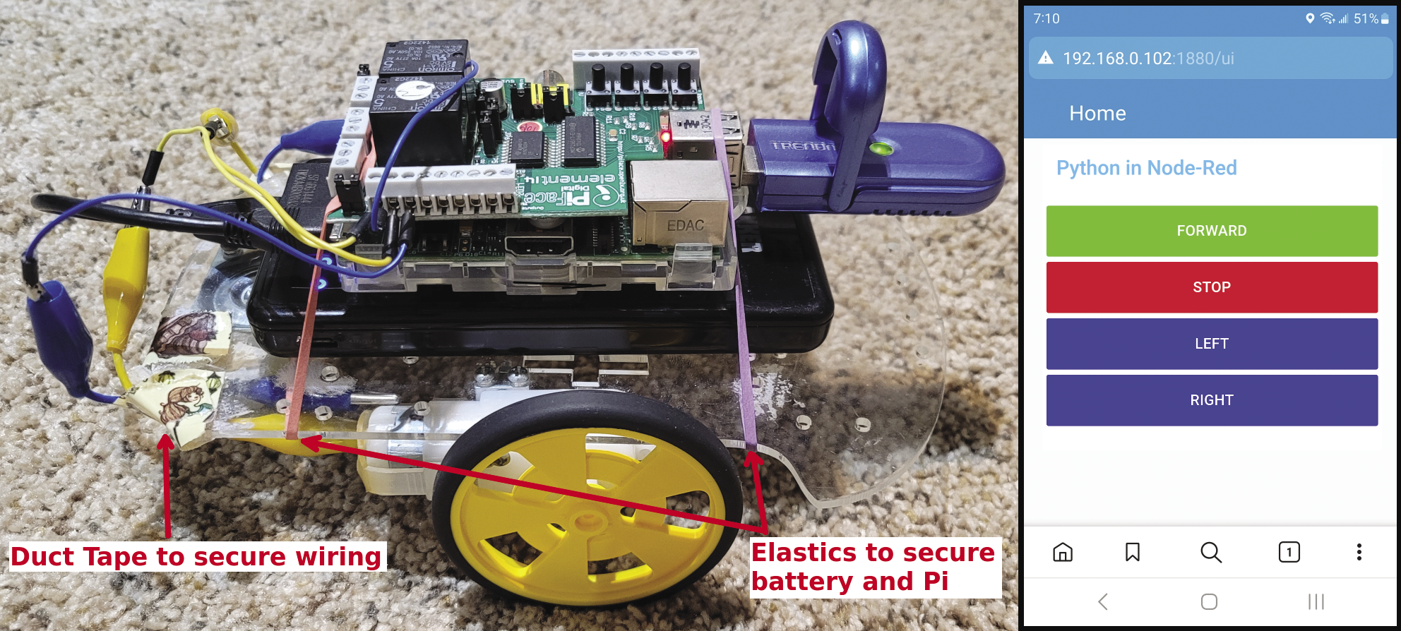
The two-motor car chassis usually comes without any wiring on the motors. For a quick setup, I use a combination of alligator clips and jumper wires to connect the motor terminals to the Pi motor shield. A couple of strips of duct tape are useful for holding the wires in place. Finally, elastic bands keep the portable battery and the Raspberry Pi attached to the chassis.
To test the hardware setup, I found it best to keep the car chassis raised with the wheels off the ground. This step allowed me to use a standard power plug without killing the battery before I was ready to play. You might have to adjust the wiring to ensure the motors are both turning in the required direction.
The first software step is to install your motor’s Python library. (Note: This step will vary depending on your motor shield.) For my hardware, I installed the PiFace library with:
pip install pifaceioAt this point, you should test the hardware directly with Python. Check your hardware documentation for some sample code to turn the motor on and off.
To test a single motor with Python within Node-RED, four flows are used: two inject, one python-function-ps, and one debug (Figure 3). A debug flow isn’t required, but it’s useful to verify that the Python code runs cleanly. The inject flows create a message payload with either a numeric 0 or 1 to stop or start the motor.
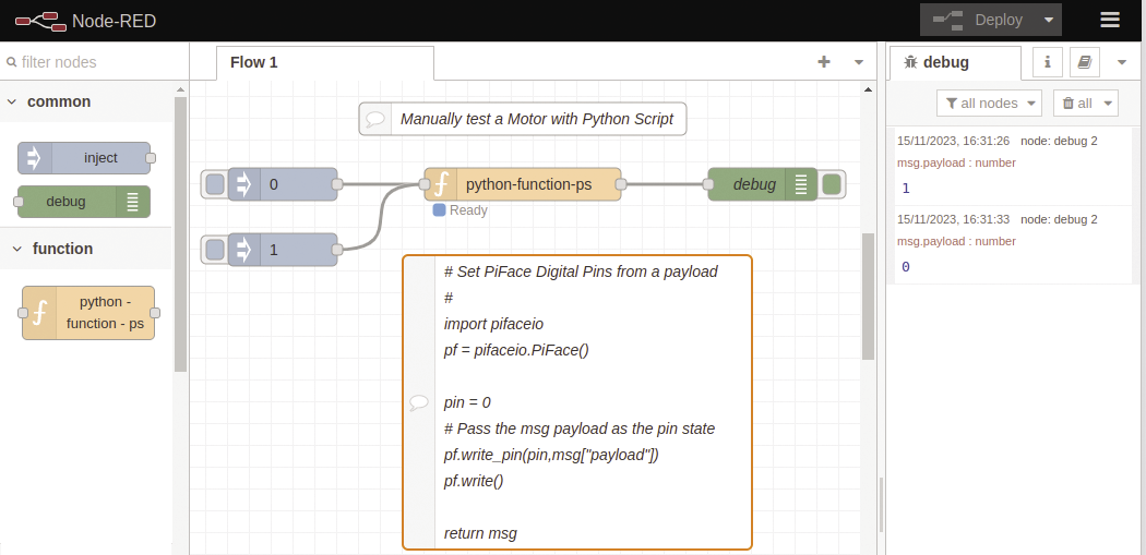
In the python-function-ps flow, the incoming Node-RED message (msg) is accessed as a Python dictionary variable. The following Python examples read, set, and clear the Node-RED message:
# get the message payload
themsg = msg['payload']
# set the payload
msg['payload'] = "Good Status"
# create a new message item
msg['temperature'] = 23.5
# clear the entire message
msg.clear()
For the PiFace library, my code needed to do a write_pin command to set a specific pin. A write command then outputs the request states for all the pins. To set pin 0 to the incoming payload message, use:
pin = 0
# Pass the msg payload as the U
pin state
pf.write_pin(pin,msg["payload"])
pf.write()
Once the basic testing is complete, the next step is to define a Node-RED dashboard with buttons to control the rover.
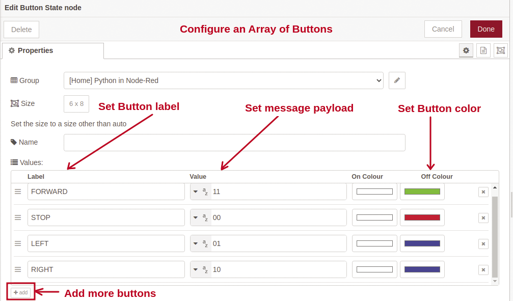
The final Node-RED logic for this project only requires two widgets: The Button State component creates an array of user buttons, and python-function-ps runs the Python code to control the motors (Figure 4).

The Button State widget is edited with a double-click. Multiple buttons can be added with custom labels, payloads, and colors (Figure 5). A simple two-character string is used for the buttons’ message payloads, with the first character being the LEFT motor state, and the second being the RIGHT motor state. A FORWARD command sets both the LEFT and RIGHT motors to 1, with a payload of 11. A STOP command sets both motors off with a 00 payload. It’s important to note, that to turn left, the left motor needs to be turned off and the right motor needs to run – and vice versa for turning right.
The python-function-ps flow (Listing 1) imports the Python pifaceio library (line 4) and creates a pf object (line 5). Next, the button payload passed in is parsed to make two variables: the LEFT and RIGHT requested motor state (lines 8 and 9). Lines 13-15 write the motor states.
Listing 1: Python Control Code
01 #
02 # Set PiFace Digital Pins
03 #
04 import pifaceio
05 pf = pifaceio.PiFace()
06
07 # Get the Left and Right requested state
08 LEFT = int(msg["payload"][0])
09 RIGHT = int(msg["payload"][1])
10
11 # Set the left and right pin motor values
12 #   the left motor is on pins 0 and right is on pin 1
13 pf.write_pin(0,LEFT)
14 pf.write_pin(1,RIGHT)
15 pf.write()
16
17 return msg
Figure 6 shows the Node-RED dashboard and the rover with a PiFace Digital module mounted on a Pi 1. Future enhancements to this project could take advantage of motor shields that support reverse motor directions or variable-speed motor settings.
Sensor Project
You have the choice of an excellent selection of Raspberry Pi Python starter projects, but communicating with sensors and I/O are usually good places to start for people interesting in building IoT projects.
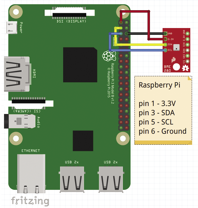
In this second project, I look at acquiring temperature and humidity data from a BME280 sensor (~$5); however, if you have a different sensor, you should be able to adapt this project to your needs. For the programming, you gather the sensor data in Python, and the real-time scheduling and the web dashboard are created in Node-RED. The BME280 sensor is connected to the Pi over inter-integrated circuit (I2C) connections. The serial data (SDA) and serial clock (SCL) are on Raspberry Pi pins 3 and 5 (Figure 7).
The first step in this project is to enable I2C communications and then install a Python BME280 library:
# Enable I2C, 0 = enable, 1=disable
sudo raspi-config nonint do_i2c 0
# Install Python BME280 library
pip install RPI.BME280
BME280 sensors are typically on addresses 0x76 or 0x77. To verify the address, use the i2cdetect command-line tool:
# Scan for I2C devices
$ i2cdetect -y 1
To ensure that the sensor, I2C communications, and Python library are all working, create a Python test program (Listing 2). If everything is hooked up and working correctly, some values should appear:
# Check BME280 setup with a Python U
test app
#
$ python3 bme_test.py
Temperature: 20.943249713495607
Pressure: 996.5068353240587
Humidity: 52.84257199879564
Listing 2: Test BME280 Sensor
01 # bme_test.py - Show values from a BME280 sensor
02 #
03 import smbus2
04 import bme280
05
06 # BME280 sensor address (default address could be: 0x76)
07 address = 0x77
08
09 # Initialize I2C bus
10 bus = smbus2.SMBus(1)
11
12 # Load calibration parameters
13 calibration_params = bme280.load_calibration_params(bus, address)
14
15 # Get sampled data
16 data = bme280.sample(bus, address, calibration_params)
17
18 print("Temperature: ", data.temperature)
19 print("Pressure: ", data.pressure)
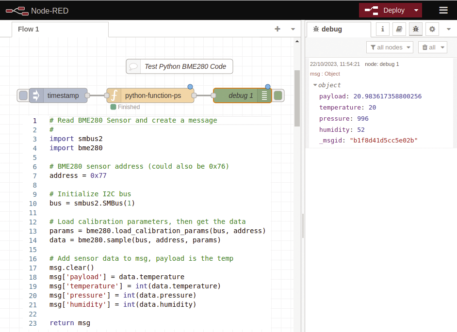
20 print("Humidity: ", data.humidity)This Python code can be moved and tested in the Node-RED environment with inject and debug flows (Figure 8). A slight modification to the code in Figure 8 (lines 17-21) passes the sensor results to the dictionary msg variable instead of doing a print statement as in Listing 2. The debug flow is defined to show the complete message, so the debug pane shows all the sensor results.
The next step is to show the results in a web dashboard, which includes the addition of two new widgets. The first new addition is an old-style mercury thermometer widget (ui-widget-thermometer), and the second is a scheduler (bigtimer). Note that it might be useful to include the Node-RED BME280 component for a comparison check.
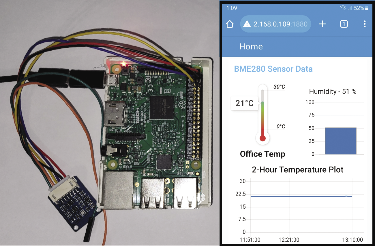
The final application (Figure 9) uses the same Python code as in the earlier test circuit, but a bigtimer widget schedules its execution. Although this widget has excellent scheduling functionality, to keep things simple, you can just use the widget’s middle output to send a pulse every minute.
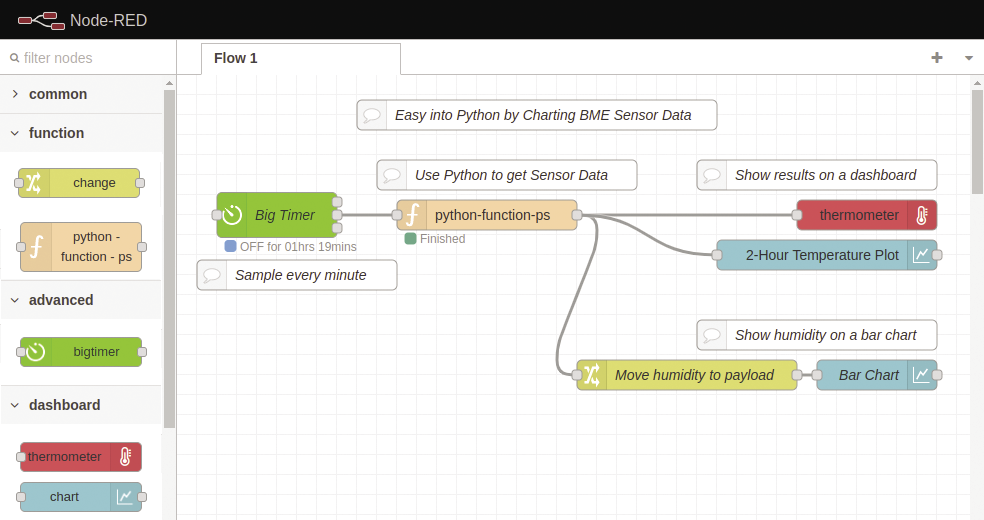
The thermometer flow shows the temperature value, which is the payload message from the Python code. A chart widget reads the same temperature value and presents the results in a two-hour line plot. A change flow moves the humidity to the message payload (Figure 10), which allows a second chart to show the humidity in a bar chart.
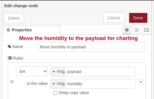
Figure 11 shows the Node-RED BME280 dashboard with the Raspberry Pi and sensor setup. This project could be enhanced to show the results from multiple sensors.
Summary
Python scripting in Node-RED offers new programmers a great way to build some interesting applications without getting too bogged down in graphical interfaces. In a few cases, the python-function-ps widget crashed. For me, this occurred with hardware-specific libraries like pyusb. A good work-around is to use the built-in exec component, which can run an external Python program. The exec widget supports appending message payloads to the called program string.