Where in the World
Design and construct a battery-powered GPS receiver and recorder in a compact package, with firmware and a Linux-based GUI application for visualizing the data recorded.
A variety of solutions are available for tracking the location of things, such as locating “lost” items (e.g., smart dog collars) or locating your luggage (e.g., Apple AirTags). All these devices have to balance functionality, size, weight, and time of battery life (rechargeable or otherwise). A mobile phone makes a pretty good location device, because it has a GPS receiver and a radio transmitter. However, they are relatively large, are expensive, have unnecessary components (e.g., displays), and rely on a cellular network that might not be available in remote areas.
Apple AirTags rely on Bluetooth communication with other Apple devices in the vicinity to provide position information and relay that data to iCloud, which the user can access with the Find My app. This useful function allows the tags to be very small and operate from a small button cell battery. The drawback to this method is its reliance on other devices and, again, the presence of a cell network.
The device presented here is completely autonomous; the size of a matchbox, weighing less than 50g (<2oz), and has its own GPS receiver, a LiPo battery providing several days of operation, and flash memory to store the acquired GPS data. Because GPS coverage is worldwide in its various forms, no other infrastructure is required for operation.
The downside is that the data is only available when the device is returned to the user. This compromise will be acceptable for some applications, but not others. It would be possible to combine this design with a low-power sub-gigahertz radio transmitter – for example, 868MHz LoRa (long range) – but for a useful range, the device would have to be significantly bigger and heavier because the radio would need power to transmit messages.
One potential application of the current design would be tracking the movements of a domestic pet, an animal in a zoological park, or the migratory patterns of wildlife. I personally use the device to record hikes, because the maps overlaid with the track provide a concise reminder of the route taken.
In common with all GPS devices, the receiver requires an unobstructed view of the sky, and concealed use is rarely practicable, so its use as a plot device in many movies is inaccurate in this respect. In a car, for example, the built-in GPS receiver commonly referred to as the satellite navigation (satnav) system is typically installed on the dashboard or part of the rear-view mirror assembly at the top of the windscreen, where it has a clear view.
Also worth noting is that reflections of the GPS signal from buildings and trees can lead to spurious location data, so some interpretation of the results may be required. Some sophisticated devices incorporate inertial navigation devices (gyroscopes and accelerometers) to augment data accuracy.
Hardware Design
The completed design, both hardware and software, can be found on my GitHub page. The core of the system is an STM32 microcontroller, specifically the STM32F072CBT6. Because of the huge variety of microcontrollers on the market, the choice of an appropriate device can daunting. Previous experience tells me that STMicroelectronics (ST) devices perform well at a good price point and are very well supported in terms of development tools and online resources. Having designed a great many projects around these devices, I also know that software development will be accelerated by my familiarity with the STM32 family and their development tools.
This project could just as easily have been based on an Arduino, a PIC, or a Pi Pico, but as I say, choice comes down to familiarity and suitable package configurations with the required I/O. The key features required in this case are low power, small physical size, a real-time clock, and USB and serial peripheral interface (SPI) connectivity.
Schematic capture and printed circuit board (PCB) layout were both performed by KiCad, a free and open source computer-aided design (CAD) tool originally developed at CERN. KiCad really is an excellent suite of tools and handles the whole process of electronic design from schematic capture right through to generating files for manufacture. A 3D viewer generates an image of your design that you can pan and rotate, including the components.
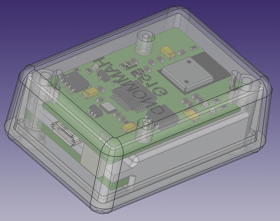
Although PCB layout is in 2D, the ability to add 3D models of all the components and view the PCB assembly in a 3D viewer has saved me from mechanical clashes that are not apparent from the 2D design perspective. You can export the 3D model as a STEP file and import that into 3D CAD tools, such as FreeCAD, to build up more complex assemblies, aiding in the design of parts suitable for 3D printing (e.g., enclosures).
Many excellent online PCB companies build good-quality PCBs in a few days for less than $5 (EUR5, £5), so building prototype or experimental PCBs is not prohibitively expensive. Once the PCB design is complete in KiCad, a 3D model of the PCB assembly is exported into FreeCAD and an assembly created of the case to ensure all the assumptions about dimensions are correct.
The 3D model ensures all mechanical dimensions match up. The case in Figure 1 is shown in transparent mode with the location of the USB connector and the battery. The model identified a collision between the battery connector (to the right of the USB connector) and the battery itself. The solution was to omit the connector and solder the battery leads directly to the PCB. Because the battery is rechargeable, it should not require changing.
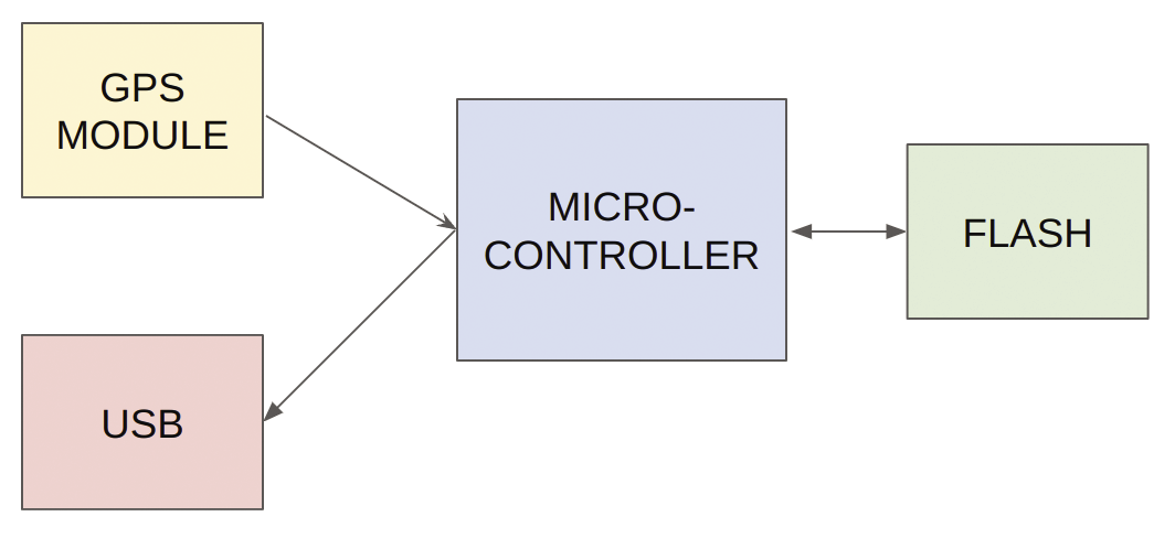
The microcontroller connects to the GPS module with a serial universal asynchronous receiver/transmitter (UART). It connects to 4MB flash memory over an SPI bus and provides a virtual serial port connection to the host. Five volts of power is delivered over the USB interface and is used to charge the 3.7V LiPo battery via a charger chip. A low-dropout regulator provides the system with 3.3V from the raw LiPo voltage, powering the microcontroller, the flash memory, and the GPS module.
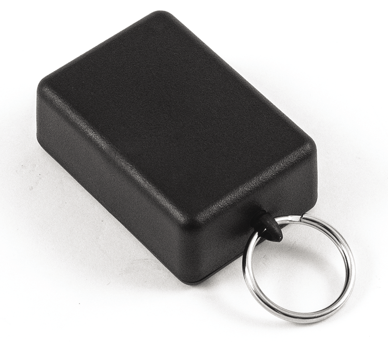
The on-board battery charger manages the charge state of the LiPo battery, which is small enough, at 45x25x8mm (1.75x1x0.25 inches), to fit into the smallest plastic enclosure I could find, at 50x35x20mm (2x1.5x0.75 inches) (Figure 2) and still leave room for the PCB with all the circuitry. The battery charge power is derived from the USB interface. Once disconnected from the USB host, the unit runs for more than 72 hours of continuous recording at 10-second intervals, without resorting to any power management in the firmware.
Battery life could definitely be extended by implementing a sleep/wake cycle, at the expense of longer periods between data acquisition. Because data is written directly to flash memory, no data is lost if the battery runs out of charge. Finally three LEDs are provided to indicate the charge status, GPS fix obtained, and GPS message reception.
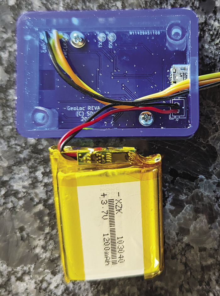
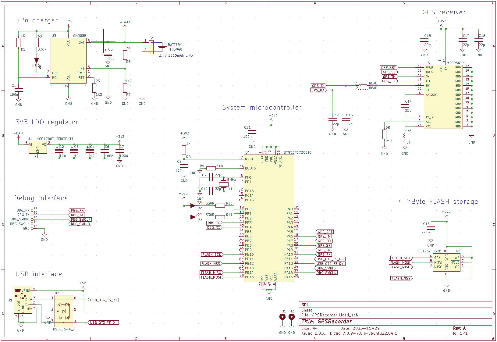
The complete assembly is shown in Figure 3. The extra wires are for a debugger and can be removed once the firmware is downloaded and debugged. The full schematic for the final design is shown in Figure 4.
Firmware Development
The use of integrated development environments (IDEs) can be controversial and very much a matter of taste, and it’s certainly possible to do this type of microcontroller development without one. The ARM compilers and standard libraries can be downloaded from your distro’s repository, and you’re off, with the use of any editor that suits you and make or cmake – again, your choice.
Once you have a compiled binary, ST-LINK utilities allow you to program your device, and you can use the GNU debugger (gbd) to debug you program. If you don’t want to use the hardware abstraction layer (HAL) libraries provided by ST, you can generate your own header files with the addresses of the microcontroller registers and all the bit patterns required for configuration.
That said, ST’s C/C++ development platform, STM32CubeIDE, which is based on Eclipse, does streamline the process by integrating the STM32CubeMX tool, a utility that allows you to configure your microcontroller and generate a software framework that does all the initialization and leaves you with a blank main() function, to which you add your own code. The HAL libraries hide a lot of the complexity of setting up some of the peripherals but are not perfect, so they must be used with caution. A number of online resources show how to use the IDE to set up the clocks, UARTs, timers, USB ports, and the like on an STM32 processor, including ST’s own getting started guide.
Figure 5 shows the pin configuration for this design and an example of a universal synchronous/asynchronous receiver/transmitter (USART) setup. Once saved, the IDE will then generate a set of #define directives for the I/O pins that you can use in your code and a complete set of initialization routines.
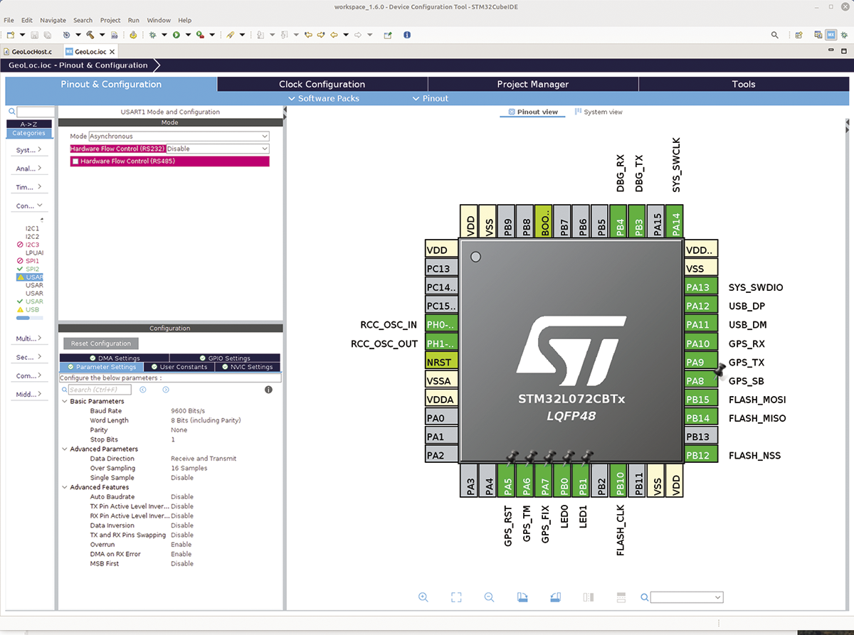
At this point, you can continue to use the IDE or ignore it and use make with the generated makefile. However, if you stay with the IDE and have your hardware connected in an ST-LINK programmer, a single mouse click in the IDE build menu, or a keyboard shortcut will compile, download, and run your code. This level of pre-configuration – including, if you like, the inclusion of a real-time operating system (RTOS, e.g., FreeRTOS) – can leave you free to concentrate on your application code. In a commercial environment, time to market is everything, and time savings like this can be invaluable.
Firmware
The firmware manages the initialization of the external devices (GPS, flash), its internal USB port, and other peripherals. After the initialization, the firmware manages data flow from the GPS receiver to flash memory (Figure 6) and, when the device is connected to USB, responds to commands sent over the virtual serial bus to deliver data to a host computer.
The GPS module has a UART interface that operates by default at 9600 baud. Once powered up, the module starts to emit GPS “sentences”, which contain status and location information. It is possible to configure the module by sending configuration packets – for instance, to change the frequency of the location updates. Messages in both directions are checksummed; a calculator to check the checksum calculations is available.
All the incoming sentences are timestamped, and this time is used to set the system clock, as well as to generate date-based file names for storing the location data. The data is in ASCII format, which means it is human readable, and is received by the microcontroller in an interrupt service routine (ISR). A typical burst of sentences that arrive at n-second intervals may be as much as 500 bytes, although much of this is discarded or suppressed by configuration. In any case, the processing required is too complex to be performed by the ISR, so it’s put in a queue.
The main program loop checks the queue at regular intervals, pulls off and processes any data available, and, if appropriate, writes the digest to flash. The “elasticity” provided by the queue means the main program loop is busy (e.g., sending data over USB); incoming data will not be lost. Listing 1 shows the debug data available at the console and a complete GPS sentence.
Listing 1: Debug Data and GPS Data
$ fix data became valid time and date set to 082853.000 on 020124
$ $GNRMC,082903.000,A,5120.7303,N,00042.7242,W,1.27,209.74,020124,,,A*6F
The microcontroller communicates with the external 4MB flash chip over an SPI bus. SPI commands include reading and writing sectors, erasing the entire chip, and erasing blocks of memory for reuse. Flash write operations are relatively slow, so again, it is useful to be able to buffer the incoming data.
The incoming data from the GPS receiver is parsed to extract the data of interest, balancing completeness of data against storage requirements in flash. I decided to store the data in ASCII to avoid conversion and so that the data remains human readable. Each GPS location message received is reduced to five numbers stored in tab-separated records (Listing 2): a timestamp, latitude, longitude, speed, and heading. The last two are not strictly necessary but do help weed out the more obvious erroneous data.
Listing 2: Tab-Separated Location Data
84551 51.345459   ‑0.711883   0.236644 122.980003
84601 51.345448   ‑0.711883   0.920855 135.509995
84611 51.345440   ‑0.711855   0.468144 155.309998
84621 51.345444   ‑0.711878   0.318955 240.389999
84631 51.345470   ‑0.711900   0.241789 203.100006
A filesystem is employed to simplify and organize the storage of the GPS data on the flash device. A number of open source implementations of filesystems for embedded flash devices and SD cards are available; I chose littlefs [14] because it implements flash wear leveling. The other flash filesystems available for STM architectures, notably FatFs, an implementation of the venerable FAT filesystem, is more suitable to removable SD cards because the lack of wear leveling will cause the card to fail eventually.
Littlefs provides a familiar Unix-like programming API with function calls such as open, read, write, close, mount, format, and so on. Porting it to the unit’s flash memory involves setting some size parameters in a configuration file and providing low-level (SPI) read, write, and erase routines to interface to the flash memory.
One part of the GPS message that is not stored explicitly is the “fix obtained” flag, which is set once the GPS receiver can see sufficient satellites to be confident in its data. The flag is used as a trigger to set the system clock from the GPS data. From that point on, the parsed data is appended to a file with a name of format DD_MM_YY, so when the clock rolls over at midnight a new file is created and recording continues.
Over time, the root of the filesystem fills with files containing each day’s GPS records. At around 50 bytes per record, that’s about 10 days of data for the current flash chip if recording continuously. Of course, much bigger devices are available, and for the current design, going from 4 to 16MB is possible without relaying out the board. The host application described later allows the user to archive and offload data files for later review, thus freeing up flash memory for more data.
Listing 3 shows the routine that processes GPS messages from the queue and writes the processed data to the current file (Figure 7).
Listing 3: Processing GPS Messages
01 /** */
02 void gps_process_msg(void)
03 {
04   static uint8_t buffer[512];
05
06   static bool fix_valid = false;
07   while(queue_size(queue))
08   {
09     queue_get(queue,buffer, sizeof(buffer));
10
11     char time[16];
12     char date[16];
13     char latitude[16];
14     char longitude[16];
15     char speed[16];
16     char course[16];
17     char valid, ns,ew;
18
19     if(debug)
20     {
21       printf("%s\n$ ", buffer);
22     }
23
24     if(check_crc(buffer, sizeof(buffer)))
25     {
26       int n = sscanf((char *)buffer,"$GNRMC,%[^,],%c,%[^,],%c,%[^,],%c,%[^,],%[^,],%[^,]",time, &valid, latitude, &ns,longitude, &ew, speed, course, date);
27
28       if(n >= 2 && valid == 'A')
29       {
30         if(!fix_valid)
31         {
32           fix_valid = true;
33           set_time_and_date(time, date);
34
35           if(debug)
36           {
37             printf("fix data became valid time and date set to %s on %s\n$ ", time, date );
38           }
39         }
40
41         float decimal_latitude = nmea_to_decimal_degrees(latitude, ns);
42         float decimal_longitude = nmea_to_decimal_degrees(longitude, ew);
43         float decimal_speed = atof(speed);
44         float decimal_course = atof(course);
45         char buffer[330];
46         int length = sprintf(buffer,"%.6s\t%12.8f\t%12.8f\t%12.8f\t%12.8f\n", time, decimal_latitude, decimal_longitude, decimal_speed, decimal_course);
47
48         append_to_current_file(buffer, length);
49       }
50
51       if(n < 2 || valid != 'A')
52       {
53         if(fix_valid)
54         {
55           fix_valid = false;
56           if(debug)
57           {
58             printf("fix no longer valid\n$ ");
59           }
60         }
61       }
62     }
63   }
64
65   // turn on an LED when fix obtained
66   HAL_GPIO_WritePin(LED1_GPIO_Port, LED1_Pin, !gps_get_fix_obtained());
67 }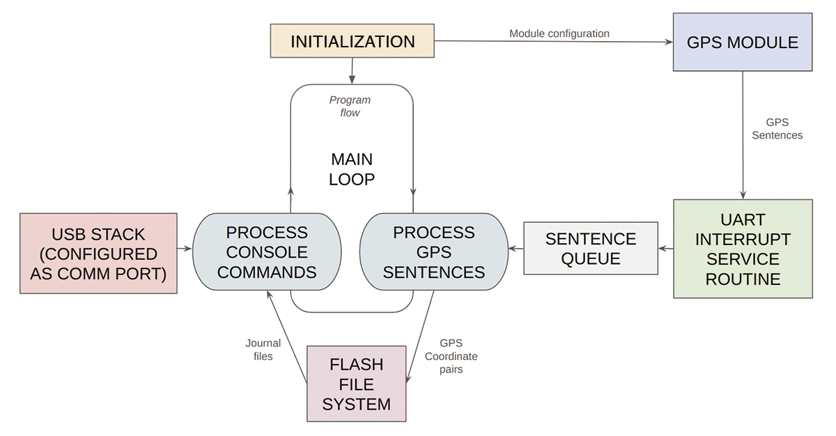
It is apparent that some conversion of coordinates in GPS sentences is taking place from NMEA format to decimal (Listing 4). NMEA format is (d)ddmm.mmmm, where d is degrees and m is minutes. East or west are specified in another field in the sentence.
Listing 4: Coordinate Conversion
01 /** */
02 static float nmea_to_decimal_degrees(char *nmea,char nsew)
03 {
04   float decimal = 0;
05   if(strlen(nmea)>5)
06   {
07     char integer_part[3+1];
08     int digit_count = (nmea[4] == '.' ? 2 : 3);
09     memcpy(integer_part, nmea, digit_count);
10     integer_part[digit_count] = 0;
11     nmea += digit_count;
12
13     decimal = atoi(integer_part) + atof(nmea)/60.0f;
14     if(nsew == 'W' || nsew == 'S')
15     {
16       decimal = ‑decimal;
17     }
18   }
19   return decimal;
Linux-Like Console
The USB interface is configured as a virtual serial port, and on Linux systems it will appears as /dev/ttyACM0 (or /dev/ttyACM1, etc.). You can connect to this port from a Linux host with a terminal emulator (e.g., Minicom) or programmatically with the usual file semantics (e.g., open/read/write/close). Later you’ll see how you can use this to your advantage.
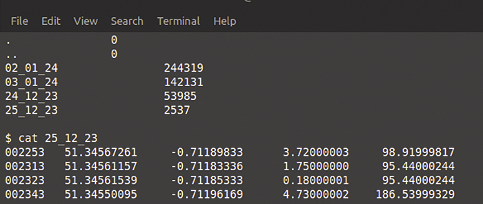
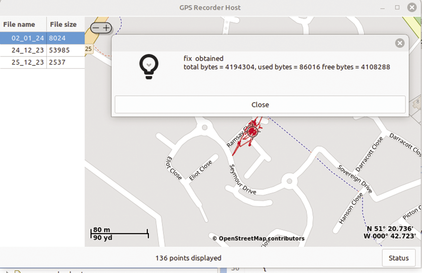
The firmware implements a familiar command-line interface (CLI), with a few Linux-like commands (e.g., ls, cat, rm), which are very helpful during debugging, so you know what files have been generated and can print them to the screen (Figure 8). Later on, after the graphical user interface (GUI) was developed, the same interface was used from within the Linux host, opening the USB device and issuing the same commands. Therefore, the same interface serves both as an interactive CLI-like interface and as an API that the host program can use.
Host Application
The Linux host application is written in C with GTK+ to provide a GUI. The main visual element of the application is a map overlaid with the location data in the form of a track. The maps are uploaded from OpenStreetMap (OSM) with the excellent open source library osm-gps-map. This solution was chosen over Google Maps, which requires a (paid) API key for embedding Google Maps in an external application. OSM does not have satellite image data, but the maps themselves are detailed and accurate.
All the details of loading maps are handled by this library along with rendering the maps to a GTK+ widget. You can scroll around the map, encompassing the whole world, and zoom in and out in a manner familiar from Google Maps. (The OSM library caches maps in your /tmp folder, so you might see some delay in displaying maps as you scroll outside of already cached areas.)
The API allows you to add tracks in the form of a sequence of points expressed in coordinates. Because the map notifies the application of mouse clicks and other events, if you click on or get close to a point on the track, application code displays a pop-up giving exact coordinates and a timestamp of when the point was visited.
Layout of the various GTK widgets is provided by three nested GtkBox layout widgets, arranging the file list to the left of the main map widget and the various controls below (Figure 9). A status bar at the bottom of the application window indicates the number of points loaded to form the current track, and a status button to the right gives live information of free space on the flash drive and the status of the GPS module.
When the application starts, it checks for the presence of the device by attempting to open /dev/ttyACM0. If the device is available, the application issues the ls command to get a list of files available on the device, named in the form DD_MM_YY, so the date of interest is easy to identify. These file names (and their sizes) are displayed in a list to the left of the application.
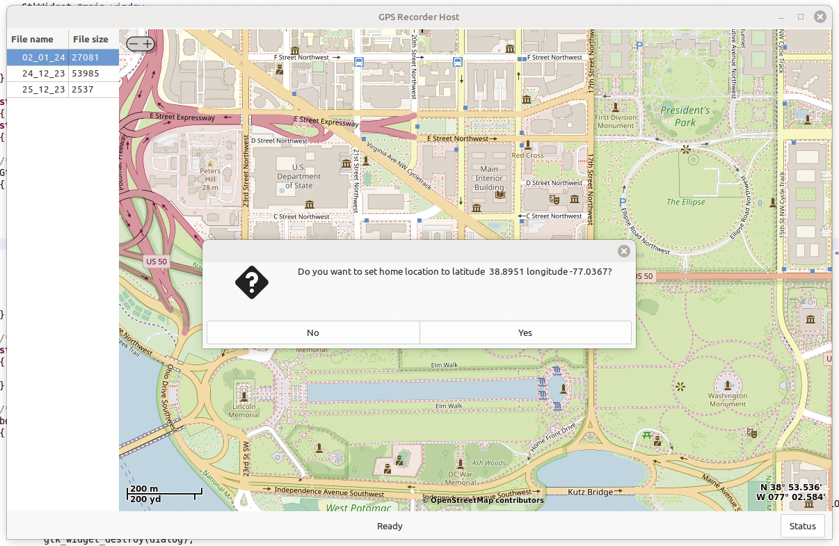
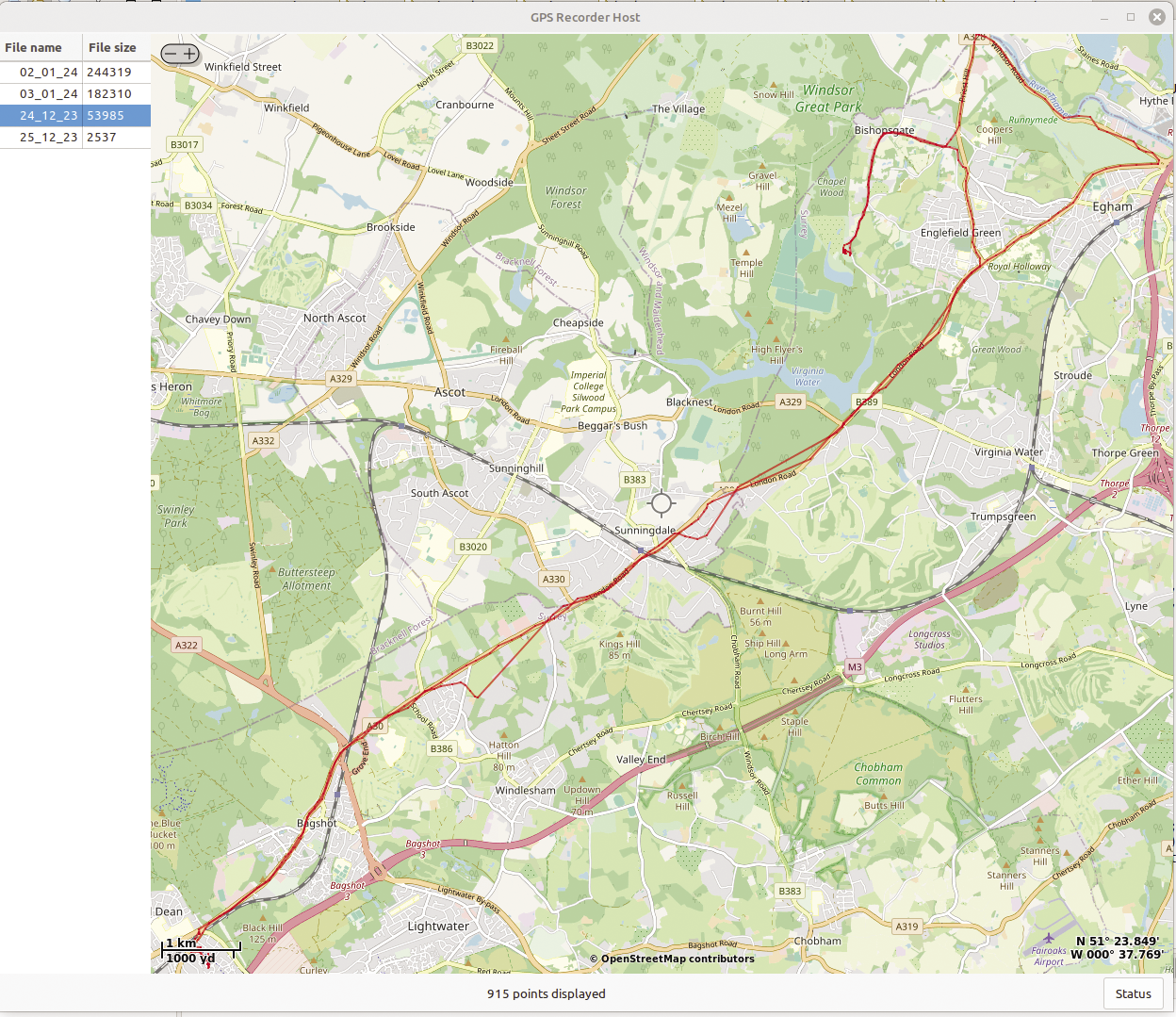
If you right-click on a selected file, a pop-up menu appears allowing you to delete a file or save it to the local disk in a file-chooser window. Double-clicking on the selected row will cause the location data to be plotted on the map to the right. The map’s home location is stored in an INI file, which defaults to Greenwich, UK, home of the prime meridian, but that can be changed at any time to anywhere in the world by double-clicking on the desired home location on the map (Figure 10). Figure 11 shows a typical track obtained from a recent car journey on Christmas Eve.
Listing 5 demonstrates communication with the device over the virtual serial link, issuing the cat command and delivering the data to the caller by way of a callback (pointer to function). The code reads each line from the file in turn until a blank line is encountered (a single carriage return character), indicating the end of the file. Listing 6 shows the use of this routine in the GUI code.
Listing 5: Retrieving Acquired Points
01 // define the callback function
02 typedef void (*pf_add_point_t)( long time, double latitude, double longitude, double speed, double course);
03
04 /** */
05 void gps_recorder_device_list_file_points(FILE * device, char *filename, pf_add_point_t add_point)
06 {
07   char buffer[64];
08   double latitude;
09   double longitude;
10   double speed;
11   double course;
12   long time;
13
14   int points = 0;
15
16   fprintf(device, "cat %s\r", filename);
17
18   while(true)
19   {
20     fgets(buffer, sizeof(buffer), device);
21
22     if((strlen(buffer) == 1) && (points > 0))
23     {
24       break;
25     }
26
27     int n = sscanf(buffer,"%ld\t%lf\t%lf\t%lf\t%lf", &time, &latitude, &longitude, &speed, &course);
28
29     speed *= knot_to_ms;
30
31     if(n == 5)
32     {
33       add_point( time, latitude, longitude, speed, course);
34       points++;
35     }
36   }
37 }
Listing 6: Putting Points on a Map
01 /** */
02 static void file_tree_view_row_activated(...)
03 {
04    ...
05   /** local function used as callback */
06   void add_point_to_map(long time, double latitude, double longitude, double speed, double course)
07   {
08     OsmGpsMapPoint *map_point = osm_gps_map_point_new_degrees(latitude, longitude);
09     osm_gps_map_point_set_user_data(map_point, (void*) time);
10     osm_gps_map_track_add_point(track, map_point);
11
12     char buffer[32];
13     sprintf(buffer, "%d points displayed", ++points);
14     gtk_label_set_text(GTK_LABEL(app_data‑>status_label), buffer);
15
16     while (gtk_events_pending())
17     {
18       gtk_main_iteration_do(true);
19     }
20   }
21
22   // call the list function passing a pointer to the local function above.
23   gps_recorder_device_list_file_points(app_data‑>device, filename, add_point_to_map);
24 }
Wrap-Up
This GPS recorder was an interesting project: Once it can see the GPS satellites, it will record its location every 10 seconds until the flash memory fills up. I think it’s sometimes very instructive to build from scratch what is a familiar item: After all, you often use satnav and phone geolocation in your everyday lives, but this project was an opportunity to deconstruct a seemingly complex system that is often overlaid with so much software and visual context that it is easy to lose sight of the underlying technology.
The host application does not process the data in any way, but you have some scope for filtering the data on the basis of speed and heading data, as well as by applying more sophisticated filtering by looking at the data as a whole rather than as discrete items. Quite a lot of information about these techniques is available, and the interested reader is encouraged to search online.