Sniffing WiFi with an ESP8266 microcontroller
The ESP8266 is in the core of many IoT devices. Thanks to ESP8266 sniffer mode, you can monitor the WiFi medium for diagnostics and optimization.
In recent years, Arduino has gained fame as the quintessential beginner’s board, but other boards with different characteristics might be more appropriate for certain projects. The ESP8266 is a system-on-chip (SoC), similar to the ATMEGA microcontrollers found on Arduino boards, but with a wireless communications module embedded within the same package.
The main advantages of the ESP8266 are its extremely low price, low energy consumption, and relatively high performance. Apart from these advantages, the availability of a platform support package for the Arduino IDE makes it extremely accessible to beginners. Although ESP8266 modules can be used as independent microcontrollers, they are often used as WiFi modems for Arduino projects because the default firmware implements an AT modem.
The ESP8266 microcontroller can be found in several form factors. One that is often used by beginners is the NodeMCU board: it is available in various variants. The NodeMCU boards are wrappers for the ESP-12 modules, which can be used in more advanced projects and final prototypes. The ESP-12 module is also in the core of the WeMos D1 board, which is designed with an Arduino Uno pinout, making it compatible with most shields.
For projects in which a small size is more important than the number of I/O pins (e.g., smart plugs), the ESP-01 module is commonly used. Finally, the ESP-05 form factor implements a universal asynchronous receiver-transmitter (UART) modem ideal for Arduino boards and cannot be programmed out of the box. In the project in this article, I use the NodeMCU v3 board (Figure 1) for its simplicity and availability. If you are programming any of the devices that do not have a USB connector, keep in mind that you will need to use a USB-UART converter and figure out the pins.
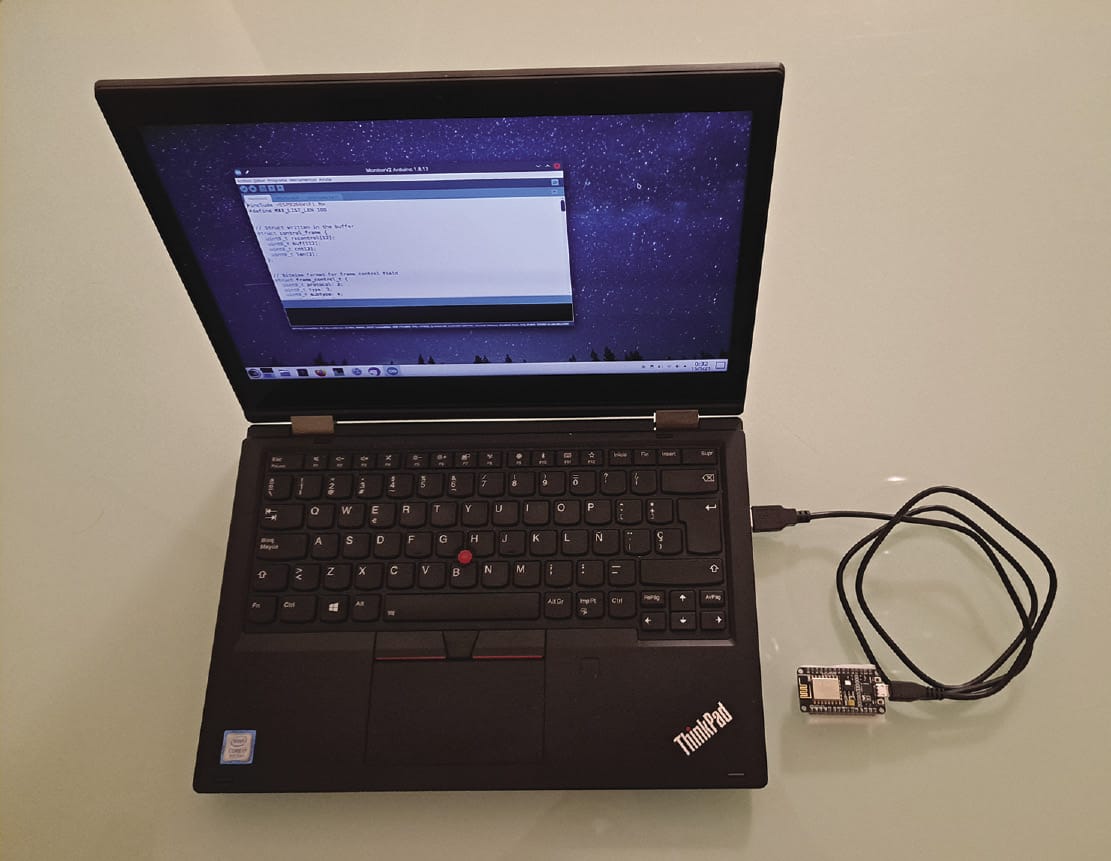
The ESP8266 offers several ways of programming. The original and default method is compiling the firmware with the standard GNU C toolchain and uploading the compiled image with a command-line application called esptool. Fortunately, much simpler ways are available, including the Arduino IDE, which I use in this article.
ays include the use of over-the-air (OTA) updates, which can be done over WiFi without having to connect the device physically to the computer used for programming (very useful for pushing updates on finalized prototypes!), or the use of tools such as ESP Easy, which allows you to configure the behavior of the ESP8266 through a web interface without programming (of course, reducing drastically the flexibility that C programming offers). Furthermore, the ESP8266 officially supports a real-time operating system (RTOS) mode officially and MicroPython, although in those cases I would recommend the more advanced ESP32 SoCs.
In this article, I use the WiFi sniffer mode (also known as monitor or promiscuous mode), which is one of the many interesting functionalities that ESP8266 offers. In this mode, the WiFi modem captures all the WiFi physical layer (PHY) packets that are in the air, regardless of which network they belong to. The device does not need to (in fact, it must not be) connected to the any of the basic service set IDs (BSSIDs) from which it is sniffing packets. This mode is normally used for network debugging or for other purposes, such as detecting WiFi stations (STAs) nearby for counting people at a specific venue.
In monitor mode, the ESP8266 listens to the medium for packets at the physical layer on one of the 11 channels (or frequencies) present in the 2.4GHz band. When a packet is detected, it is decoded at the media access control (MAC) layer and saved into a buffer along with some extra information; a callback is then invoked to process the frame.
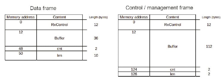
Depending on the frame type, the buffer will have different contents (see the “The MAC Layer” box). In the technical reference for the ESP8266, a code listing shows the contents of this buffer depending on the type of frame. Figure 2 shows the contents of the buffer for different frame types. The RxControl field contains data such as the received signal strength indicator (RSSI) or the modulation coding scheme (MCS, for IEEE 802.11n). The buf field contains the first bytes of the captured datagram. In the case of data frames, only the first 36 bytes are saved (i.e., the frame header). In management and control frames, 112 bytes are saved containing the header and part of the body. The cnt field shows the number of captured frames, which is greater than 1 only for aggregated data frames (a method for including several MAC frames into a single PHY packet for higher efficiency). The len field in the management frame buffer indicates the total length of the frame, and the LenSeq array indicates the same plus additional information for data frames.
The sniffing described in this article occurs at the MAC layer, which is a sublayer of the Link layer. The MAC layer in IEEE 802.11 performs several functions related to the radio access service provided by the PHY layer. First, the MAC layer orchestrates access to the medium through the carrier sense multiple access with collision avoidance (CSMA/CA) protocol.
Second, the MAC layer defines an addressing scheme, wherein each terminal uses a unique identifier to send and receive datagrams. MAC addresses are made up of 6 bytes and represented by 12 hexadecimal digits. The MAC address of an access point (AP) is also the BSSID of a basic service set (BSS). The BSSID is completely different from the service set ID (SSID): It cannot be customized, it is used only at the MAC layer, and it is different for each AP of an extended service set (ESS).
Third, the MAC layer provides a set of frame definitions that define a structure for the transmitted data. Specifically, three types of frames are defined in IEEE 802.11:
• Data frames carry user data from the network layer, normally consisting of Internet protocol (IP) datagrams.
• Management frames carry the control plane messages that perform all the functionalities required to create and maintain wireless local area networks (WLANs). Some notable examples are the beacon frames, which are transmitted by APs broadcasting their capabilities, SSID and other IDs, and association request and response frames, which are used to establish a connection to a BSS and other service sets.
• Control frames are part of the CSMA/CA protocol and are used for coordinating access to the medium.
SSID announcements occur with management frames. Specifically, a beacon frame is the management frame used for an SSID announcement. Beacon frames contain all the information that a non-connected STA would need to know to connect. In a BSS, the beacon frame is transmitted only by the AP, whereas in an independent BSS (IBSS , also known as ad-hoc networks), it is transmitted by all the STAs. The beacon frames are transmitted regularly (about 10 times per second) for devices that are scanning passively to discover nearby networks. Alternatively, STAs may discover networks by actively sending probe requests (another subtype of management frames), to which probe replies are returned (containing the same information as beacon frames). Here, I collect the beacon frames and get a list of visible service sets (i.e., a list of SSIDs).
Figure 3 shows the format of a frame. Each frame is made up of three main parts: the MAC header, which contains metadata for the MAC layer of the networked devices that informs what to do with the packet; the body, which contains the higher layer data; and the frame check sequence (FCS), which detects transmission errors.
The header, in turn, is divided into six fields:
• Frame control (2 bytes) contains data such as the protocol version or whether the message is a retransmission. I am interested in the type and subtype fields, which I will use to filter the type of frames I will be sniffing.
• Duration or ID (2 bytes) is a multipurpose field, depending on the type of frame. In some cases it is used to communicate to STAs in power save mode that a frame awaits them. In others, it communicates the duration of the acknowledgement frame that the receiver will send for the current frame.
• Address fields (6 bytes each), of which there are three (1, 2, and 3), have content that depends on the values of the To DS and From DS bits in the frame control field. In beacons, address 1 represents the destination address (DA), which is the broadcast address (all bits set to 1); address 2 is the source address (SA), which is the MAC address of the transmitting AP; and address 3 is the BSSID.
• Sequence control (2 bytes), when the higher layers are transmitting a datagram that is longer than the maximum size the MAC frame can transmit and is divided into fragments, organizes fragmentation and ensures re-assembly on reception.
In beacon frames, the body contains the information about the service set so that nearby devices listening can connect. Figure 4 shows the structure of the first bytes of the beacon frame body. I am interested in the SSID field, which is variable and contains three subfields: an ID field (1 byte), which identifies the contents of the field (all zeroes for SSID); a size field (1 byte); and a variable field of up to 32 bytes containing the SSID. There are no restrictions on the contents of the SSID, so it can contain non-printable characters. The SSID can even have all null characters, in which case it is called a hidden SSID.


Setting Up the Environment
Now you need to get your Linux environment up and running for programming the ESP8266. The first step is, of course, installing the Arduino environment if you don’t have it already. You can either download it from the official site or use your distro package manager. In Debian/Ubuntu-, Fedora-, Arch-, and openSUSE-based distros, respectively, the commands are:
# apt install arduino
# dnf install arduino
# pacman -S arduino
# zypper in arduino
You also need to make sure your user belongs to the dialout group to access the USB TTY port:
# usermod -a -G dialout For the changes to take place, you must then restart your session. On some platforms, the user might also need to be in the lock group.
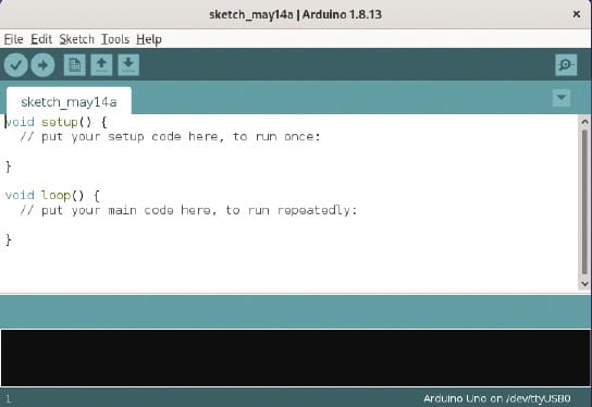
Once Arduino is installed, you need to start the IDE, which will take you to the initial screen shown in Figure 5. The Arduino IDE is rather simple, oriented to writing and uploading code without much hassle. It has some helper components, of which you will use two: the Boards Manager, which adds platform support for different hardware components, and the Serial Monitor, which establishes a UART connection with the device and lets you interact with it over the USB connection. Below the menubar is a set of shortcuts, which are, from left to right: Verify, Upload, New, Open, and Save (on the left), and Launch Serial Monitor (on the far right).
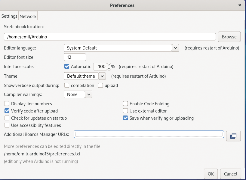
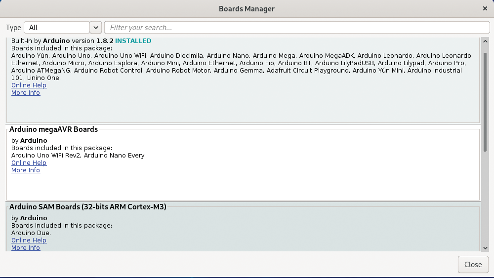
To add platform support (because Arduino IDE only supports Arduino boards by default), you have to open the File | Preferences screen (Figure 6). In this screen you configure the Additional Boards Manager URLs by adding https://arduino.esp8266.com/stable/package_esp8266com_index.json, which is the repository for platform support. After pressing OK to save the changes and exiting the Preferences window, you need to invoke the Boards Manager to install platform support under Tools | Board | Boards Manager. In the resulting dialog (Figure 7), search for ESP8266 to install the esp8266 package; exit the Boards Manager once its done.
Now that the environment is ready for programming the ESP8266, try a quick test by running the equivalent of a “Hello world” program in Arduino, which is “Blink.” This project will make the status LED of the board blink once per second.
Next, plug the ESP8266 board into the USB port of the computer and select the correct board under Tools | Board | ESP8266 boards. In my case, I’ll select NodeMCU 1.0. If you have a different board, use the appropriate entry, and in case of doubt, use the Generic ESP8266 Module option. Now load the example project from File | Examples | 01.Basics | Blink. Note the many examples that would be good starting points for your personal development. To compile and load the program, press the Upload button. After some status text in the output area in the lower half of the main window (including a progress indicator for image uploading), the new firmware will be loaded into the board and the LED will start blinking.
If you encounter a problem during the upload, check that the correct port is selected in Tools | Port and that the correct board is selected in Tools | Board | ESP8266 boards. If you get permission errors, make sure you restarted your session after adding your user to the groups.
Packet Sniffer
Now it’s time to design and write the program. The objective of the program example is simply to collect all the SSIDs that are within range of the device by capturing all the beacon frames and extracting the SSIDs. You can find simpler ways of obtaining the list of SSIDs, but in the interest of learning, I will take you the long way around.
The elements to be used are the WiFi modem configured in monitor mode to capture the frames and the serial port to display the information through the Serial Monitor. The monitor mode first must be configured in the program, including the designation of a callback. The callback is invoked each time a new packet is received. In this callback, you do all the processing and do it as quickly as possible because other packets received during the execution of the callback are dropped. The callback is a C function that receives two parameters: a pointer to a buffer where the captured frame is saved, and an integer indicating the length of captured bytes.
In this program, the first step will be to discard all the received frames that are not beacons (which are a subtype of management frames). Once you have filtered the frame type, you have to extract the information you want from its fields. For that, you have to cast the raw data in the buffer to a usable data type, but I will leave this detail for later. With the extracted information, you can either display the data to the serial port or save it into another buffer to display later. To reduce the time in the callback, I will save it until later. To display the information, use the loop() function of the program, which is external to the callback, to update the information regularly in the serial port.
Now that you have an overview of the program, you can tackle the code by creating a new project in the Arduino IDE under File | New. To begin, develop the callback shown in Listing 1 (note that the callback is defined after all the auxiliary functions), which is the main part of the program. To interpret the received buffer, you first need to be able to access the fields.
Listing 1: Callback and Auxiliary Functions
01 bool in_list(char ssid[32], int ssid_len) {
02  for (int i = 0; i < n_readings; i++) {
03
04    // If the lengths are different, go to next
05    if (readings_len[i] != ssid_len) {
06      continue;
07    }
08
09    // If the saved and new SSIDs are equal, return true
10    if (memcmp(ssid, readings[i], sizeof(char)*ssid_len) == 0) {
11      return true;
12    }
13
14  }
15  return false;
16 }
17
18 void add_reading(char new_ssid[32], int ssid_len) {
19  // Check if SSID has been seen earlier
20  if (in_list(new_ssid, ssid_len)) {
21    return;
22  }
23
24  // Reset counter if the list is full
25  if (n_readings == MAX_LIST_LEN) {
26    n_readings = 0;
27  }
28
29  // Save the new SSID
30  memcpy(readings[n_readings], new_ssid, sizeof (char) * 32);
31  readings[n_readings][ssid_len] = '\0';
32  readings_len[n_readings] = ssid_len;
33  n_readings++;
34 }
35
36 void process_frame(control_frame *pkt) {
37
38  // Convert to usable struct
39  beacon_t *beacon = (beacon_t*) pkt->buf;
40  frame_control_t fc = (frame_control_t) beacon->frame_ctrl;
41
42  // Check subtype and process further
43  if (fc.subtype == 8) {
44    ssid_t ssid = (ssid_t) beacon->ssid;
45    add_reading(ssid.ssid_str, ssid.ssid_len);
46  }
47
48 };
49
50 void callback(uint8_t *buff, uint16_t len) {
51  // Check the buffer for a control frame and process it
52  if (len == sizeof(struct control_frame)) {
53    control_frame *pkt = (control_frame*)buff;
54    process_frame(pkt);
55  }
56 }
Listing 2 contains the code for the struct that allows you to put the buffer in an appropriate format for reading the captured management frame. Note in Listing 1 that the code first checks whether the length of the buffer corresponds to a management frame; if it does not, it exits the callback. If it finds a management frame, it continues processing with the process_frame() auxiliary function. This function will receive a pointer to the buffer that contains the raw captured bytes of the frame. Again, this buffer must be cast into a usable data type before the program can access the frame fields. Listing 3 shows the three structs needed for this step.
Listing 2: Structure of Receive Buffer
01 struct control_frame {
02 uint8_t rxcontrol[12];
03 uint8_t buf[112];
04 uint8_t cnt[2];
05 uint8_t len[2];
06 };
Listing 3: Structures for Casting Captured Bytes
01 // Bitwise format for frame control field
02 struct frame_control_t {
03  uint8_t protocol: 2;
04  uint8_t type: 2;
05  uint8_t subtype: 4;
06  uint8_t to_ds: 1;
07  uint8_t from_ds: 1;
08  uint8_t more_frag: 1;
09  uint8_t retry: 1;
10  uint8_t pwr_mgmt: 1;
11  uint8_t more_data: 1;
12  uint8_t wep: 1;
13  uint8_t strict: 1;
14 };
15
16 // SSID field format
17 struct ssid_t {
18  uint8_t field_id;
19  uint8_t ssid_len;
20  char ssid_str[32];
21 };
22
23 // Beacon format
24 struct beacon_t {
25  // Header
26  frame_control_t frame_ctrl;
27  uint8_t duration_id[2];
28  uint8_t da[6];
29  uint8_t sa[6];
30  uint8_t bssid[6];
31  uint8_t sequence_ctrl[2];
32  // Body
33  uint8_t timestamp[8];
34  uint8_t beacon_interval[2];
35  uint8_t capability_info[2];
36  ssid_t ssid;
37 };
The frame_control_t struct defines the format of the control field in the header of the frame (2 bytes), where the type and subtype indicators are found. The ssid_t struct defines the SSID descriptor, which is located in the body of the beacon frame. Finally, the beacon_t struct describes the fields of the beacon frame up to the SSID.
After casting the buffer, the program can filter the frame subtype and only continues processing if it is a beacon. If that is the case, it then accesses the ssid field. The function add_reading() checks to see whether the SSID has already been saved (with the in_list() function, which searches in the readings array). If it has not, it adds the SSID to the readings array and its length in the readings_len array.
Once you have defined what to do when a beacon is received, you can deal with the rest of the logic. Listing 4 shows the setup() function, which first starts the serial port. After that, it sets the WiFi modem to an initial state, which implies putting it first into STA mode (because the ESP8266 also supports AP mode), disabling monitor mode (with wifi_promiscuous_enable(0)), and disconnecting the WiFi modem. The callback() function will be invoked when a packet is sniffed and will then start the monitor mode again. Finally, the code sets the listening channel with wifi_set_channel(current_channel).
Listing 4: setup() Function
01 void setup() {
02  Serial.begin(115200);
03
04  wifi_set_opmode(STATION_MODE);
05  wifi_promiscuous_enable(0);
06  WiFi.disconnect();
07
08  wifi_set_promiscuous_rx_cb(callback);
09  wifi_promiscuous_enable(1);
10
11  wifi_set_channel(current_channel);
12 }
Listing 5 contains the code for the loop() function, which in Arduino is run repeatedly from the time setup() is finished to the time the device is powered down. In loop(), a line is printed with hyphens and then it iterates over the full list of SSIDs. An empty line marks the end of the list. The wifi_set_channel(current_channel) line switches channels after increasing the current_channel variable, so that eventually all channels are sniffed. Next, delay(1000) inserts a 1-second delay. Finally, the initial code, containing the includes and definitions of the global variables, is shown in Listing 6.
Listing 5: loop() Function
01 void loop() {
02  Serial.println("----");
03  for (int i = 0; i <: n_readings; i++) {
04    Serial.println((char*)readings[i]);
05  }
06  Serial.println();
07  current_channel++;
08  if (current_channel == 12) {
09   current_channel = 1;
10  }
11  wifi_set_channel(current_channel);
12  delay(1000);
13 }
To put it all together, you need to write the contents of the listings into an empty main file of the Arduino IDE project in the following order: Listing 6, Listing 2, Listing 3, Listing 1, Listing 4, and Listing 5. Pressing the Upload button will launch the ESP8266 toolchain again.
Listing 6: Imports and Global Variables
01 #include
02 #define MAX_LIST_LEN 100
03
04 // Arrays for saving the SSID information
05 char readings[MAX_LIST_LEN][33];
06 int readings_len[MAX_LIST_LEN];
07 int n_readings = 0;
08
09 // WiFi channel counter (from 1 to 11)
10 int current_channel = 1;
Exploring the Surroundings
Once the upload is complete, the program starts automatically. In the Serial Monitor, you will see the output generated by the device. (To avoid a conflict, be careful not to open the Serial Monitor before the code has finished uploading.) Figure 8 shows a sample output (edited to preserve privacy).
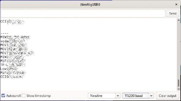
In the output, the list of devices is shown once per second. Note that the baud rate in the Serial Monitor (bottom of the window on the right side) must be 115200. The list can only hold MAX_LIST_LEN entries; if more, you lose SSIDs. Because the ESP8266, just like any other microcontroller, has a very limited amount of memory, you have to set a limit. Potentially, you could collect all the SSIDs in a file on your computer (e.g., with a Python script that reads the entries from the serial port). I will appeal to your creativity to make such a script.
Summary
In this article, I made a quick tour of WiFi, with enough depth to understand where SSIDs come from and how to extract them. I also introduced the ESP8266 microcontroller, which is a very powerful device, both for hobbysts and professionals, at an extremely low price tag. The ESP8266 comes with, among many other functions, a sniffer mode that can be used for capturing and analyzing WiFi traffic without being connected to any BSS, a very useful feature for network management and analytics.
Although the example (collecting BSSIDs) is trivial, the ESP8266 has many other uses. Some ideas that I will leave as a challenge are to use the template program shown here to analyze the number of STAs visible at a certain point or to light the LED of the ESP8266 when a specific STA is seen. Just remember always to respect privacy laws! You cannot store or share MAC addresses from personal devices of non-consenting users because they are considered private data.


