
Create a digital spirit level with the ESP32
The small MPU6050 sensor contains a gyroscope and an accelerometer, which means that you can build a digital spirit level with it.
To build a digital spirit level, you first need a sensor such as the MPU6050, which determines the position of an object in space. It has an accelerometer and a gyroscope for each axis in space and measures just 4x4 millimeters. For our test setup, we used a module to hold the semiconductor. You can get it from AZ-Delivery for EUR4.79. If it is sold-out there, you can also purchase the module on Amazon or from Reichelt.
The MPU6050 communicates with the Raspberry Pi via the I2C bus. The AD0 connector defines whether the sensor resides on bus address 0x68 (AD0 to GND) or 0x69 (AD0 to VSS). The operating voltage for the module is in the range of 3.3 to 5 volts. If you need more information about the MPU6050, take a look at the datasheet. To access the sensor, we will use a library with simple functions for accessing the sensor’s readings.
I went for an ESP32, a highly integrated microcontroller with an unbeatable price/performance ratio, to process the data from the sensor. I will be using an ESP32 development kit, which you can pick up fairly cheaply for EUR9.49. The Arduino IDE provides the development environment.
Last but not least, the project needs a display to show the measured values of the sensor graphically. An inexpensive 1.8-inch TFT color display for EUR7.99, which can be addressed via a Serial Peripheral Interface (SPI), is a good choice here. Because controlling the display is quite tricky, we will be using the GFX library from Adafruit. The library’s source code is available on GitHub.
Test Setup
The circuit diagram for our spirit level (Figure 1) shows you how to connect all the components for the project. Let’s take a closer look at the two capacitors at the very top of the schematic. The 10-µF capacitor between the EN pin and ground lets you to load the program into the ESP32 without pressing the boot button. Theoretically this should work without an additional capacitor, but practice shows that this is often not the case. The basic problem is the USB driver in combination with certain hardware components of the ESP32 development board.
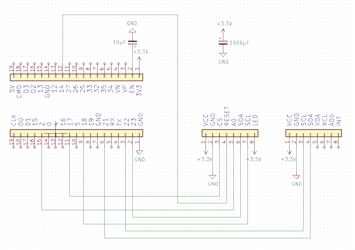
The second capacitor (1000 µF) is an option. If the backlight of the display flickers, the capacitor will eliminate this issue. It stabilizes the operating voltage, preventing the flickering. If sporadic problems occur in other digital circuits that are difficult to isolate, it never hurts to build a large capacitor into the power supply. It often helps to eliminate problems of this type.
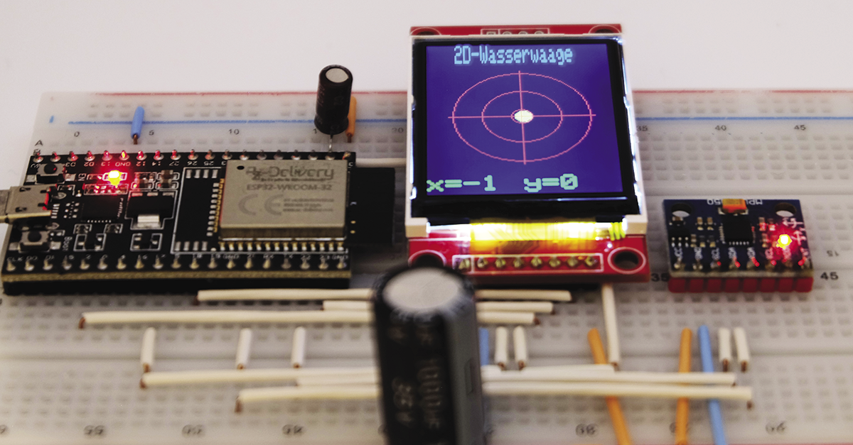
The remaining connections in the schematic connect the sensor to the ESP32 via I2C. The display uses the SPI and also comes with an additional reset connection. Be sure to connect all the power supplies present in the schematic. As Figure 2 shows, the experimental setup consists of two breadboards with the electronics. On each of the two boards, I removed one of the power supply strips to achieve a setup where the development board fits neatly, and you can easily access all the connections.
First Test
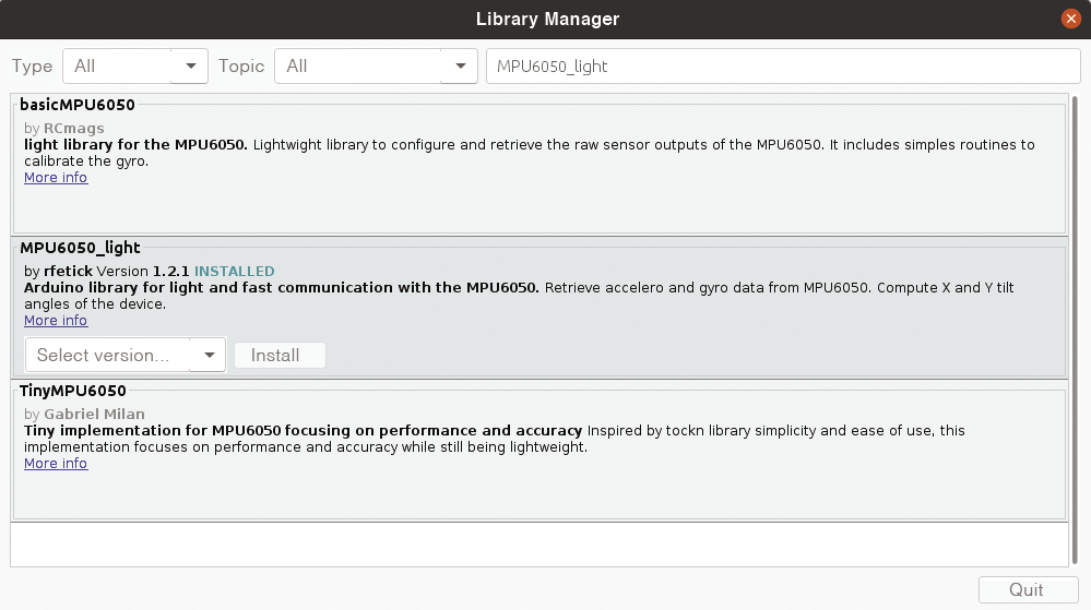
First of all, you need to start up the MPU6050 sensor. To do this, install the appropriate library in the Arduino IDE. In the menu, navigate to Sketch | Integrate library | Manage library. Once you get there, look for the MPU6050_light library and install it (Figure 3). If you are prompted to do so, install all the dependent libraries, too.
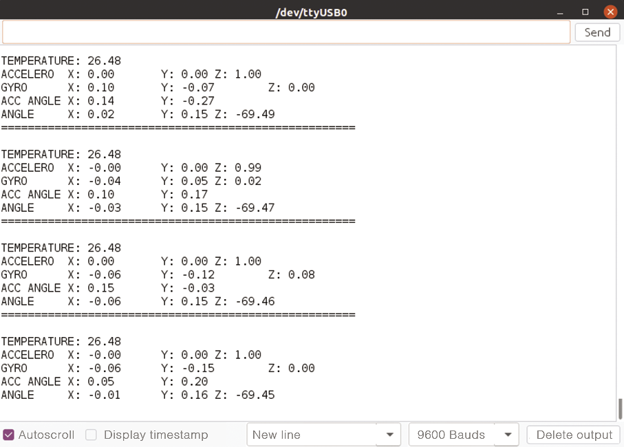
After the install you will find a sample program for reading the sensor values in the File | Examples | MPU6050_light | GetAllData menu (Figure 4). The software outputs the results of the measurements to the serial console. If you move the sensor, you can easily see how the individual values change. In addition to the data that the sensor inherently provides – acceleration in the direction of the spatial axes, angular acceleration about the axes, and temperature – it also outputs the angle of the axis as a computed value. We will be using this as the basis for our spirit level.
Testing the Display
The next step is to fire up the display. To run the display you need three libraries: TFT LCD library, Adafruit ST7735 library, and Adafruit GFX library. Install all three in the Arduino IDE as described above. Again, you may be prompted for the libraries.
After the install, go to File | Example | Adafruit ST7735 and ST7789 Library | graphicstest to find a program to test the display. To adapt it to our setup, you need to assign different values to TFT_CS, FT_RST, and TFT_DC. The code needed to do this is shown in Listing 1. Simply copy this into the program at the appropriate place. After uploading it to ESP32, a sequence of test graphics will run across the display.
Listing 1: Adaptations
// For 1.44" and 1.8" TFT with ST7735 use:
#define TFT_CS 17
#define TFT_RST 14
#define TFT_DC 2
Adafruit_ST7735 tft = Adafruit_ST7735(TFT_CS, TFT_DC, TFT_RST);
Listing 2: spiritlevel.ino
01 #include "Wire.h"
02 #include <Adafruit_GFX.h&glt;
03 #include <Adafruit_ST7735.h>
04 #include <SPI.h>
05 #include <MPU6050_light.h>
06 #define TFT_CS 17
07 #define TFT_RST 14
08 #define TFT_DC 2
09
10 Adafruit_ST7735 tft = Adafruit_ST7735 (TFT_CS, TFT_DC, TFT_RST);
11 MPU6050 mpu(Wire);
12
13 void setup(void) {
14   Wire.begin();
15   mpu.begin();
16   mpu.calcOffsets();
17   tft.initR(INITR_BLACKTAB);
18   tft.fillScreen(ST77XX_BLACK);
19 }
20
21 int x, y, xold, yold;
22
23 void loop() {
24   mpu.update();
25   x=floor(mpu.getAngleX());
26   y=floor(mpu.getAngleY());
27   if ((x!=xold) or (y!=yold)) {
28     tft.setTextSize(1, 3);
29     tft.setCursor(20, 0);
30     tft.setTextColor(ST77XX_BLUE);
31     tft.print("2D-Wasserwaage");
32     tft.fillCircle(64-x, 80+y, 12, ST77XX_BLACK);
33     tft.fillCircle(64-x, 80+y, 5, ST77XX_YELLOW);
34     tft.drawCircle(64, 80, 7, ST77XX_RED);
35     tft.drawCircle(64, 80, 27, ST77XX_RED);
36     tft.drawCircle(64, 80, 47, ST77XX_RED);
37     tft.drawLine(64, 30, 64, 130, ST77XX_RED);
38     tft.drawLine(14, 80, 114, 80, ST77XX_RED);
39     tft.fillRect(0, 142, 160, 30, ST77XX_BLACK);
40     tft.setTextSize(2);
41     tft.setTextColor(ST77XX_GREEN);
42     tft.setCursor(0, 142);
43     tft.print("x=");
44     tft.println(x);
45     tft.setCursor(64, 142);
46     tft.print("y=");
47     tft.println(y);
48   }
49   xold=x;
50   yold=y;
51   delay(50);
52 }
Spirit Level Program
After testing and performing a trial run with the components of our spirit level without any errors, it’s time to take a closer look at the program (Listing 2) for the spirit level. You will find it, along with some other files, in the download section for this article. The first block imports the required libraries (lines 1 to 5). To make the code more readable, the program then defines some constants (lines 6 to 8).
Lines 10 and 11 define the objects that we will use to address the display (tft) and the sensor (mpu). The setup() function starting in line 13 initializes all of the objects, with the calcOffsets() method to calibrate the sensor. After starting the program, it will take a while for the values to settle. The variable definitions for the measured value of the X and Y axis then follow (line 21). The xold and yold variables are used to determine whether the values changed since the last measurement. If so, the program updates the contents of the display. This procedure reduces the volume of data sent to the display to the required minimum.
The loop() function calls the mpu.update() method to start a measurement (line 24). Then the mpu.getAngleX() and mpu.getAngleY() methods read the measurement values. The library returns floating-point values, which the floor() function converts to integers. Some sensor accuracy is lost in the process, but as a positive side effect, the values will not fluctuate as much. At this point, there are certainly many solutions that offer more accurate results. But for our spirit level, this simple procedure is perfectly OK. Just bear in mind that with more overhead you can tickle more accurate values out of the sensor.
The commands in the if statement starting in line 27 update the display. What is important to note here is that the program always drops new display information on top of the existing information. This means that you can’t read older display information after some time because everything is filled up. Erasing the entire display before each write isn’t a good idea either because it causes annoying flickering.
The solution is to selectively edit the areas that change. The command
tft.fillRect(0,142,160,30,ST77XX_BLACK)in line 39 erases just the part where the measured values are shown. Parts that remain constant, such as the heading, are overwritten by the program. Apart from this, the code in this section is pretty much self-explanatory. If in doubt, consult the library documentation.
At the end of the loop() function starting in line 40, the program copies the values of the x and y variables to xold and yold. This is followed by a delay() to the flow before the program starts the next round of the loop. A YouTube video shows you how the program works.
Conclusions
This article shows how to build a digital spirit level with simple materials. All in all, there are still many options for increasing the sensor’s accuracy. A 3D printed housing for the technology would massively improve the stability of the setup.
The sample program, which is fairly simple, makes it easy to implement quite a bit more accuracy and functionality. The combination of ESP32 and the display allows for many more interesting projects to be built. All told, this is a neat project that you can learn a great deal from. I hope you makers out there enjoy building your personal spirit level.