Off to the Race Track
Build a remote control car with the Fischertechnik Maker Kit Car, MicroPython, and ESP32 microcontrollers.
Sometimes a project idea fails because of the hardware setup: Maybe the parts you chose do not match, a component you need is unavailable for weeks on end, or the design turns out to be so unstable that the whole thing unravels. Being aware of these problems, Fischertechnik offers a robust basis for building mobile robots in the form of their Maker models. You can choose which controller, which programming language, and which electronic components you want to use. You can currently get three models: a car, an omni-wheel vehicle, and a walkabout robot with four legs.
This article looks at the Maker Kit Car construction kit and how to control the model remotely using MicroPython on two ESP32 microcontrollers.
The Maker Kit Car construction kit, which costs just south of EUR100, lets you build a car model from a total of 119 parts. You can find detailed online assembly instructions that show each individual step as a small animation. If you are unsure about a build stage, you can view the model from all sides in the 3D view (Figure 1). There is only one fairly challenging build step: assembling the differential requires fiddling with small gearwheels that might fall off again.
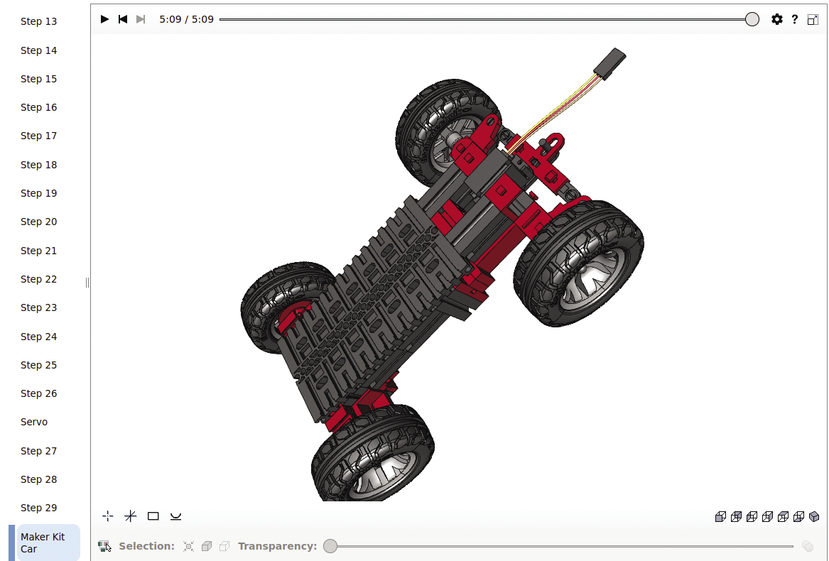
The kit contains an encoder motor and a servo motor. If you need detailed technical information on the motors, you’ll find that in the data sheet. The encoder motor acts as the drive for the car, while the servo motor is used to handle the steering. When you install the motors, make sure that the servo motor is in center position. The easiest way to do this is with a servo tester. After you have completely assembled the model, you are left with six spring cam connectors that can be used to attach various additional components to the car.
Servo Motor
The servo motors discussed in this article are the type commonly used in model making. They move a lever arm from a center position in both directions by 45 degrees. This allows for steering over an angular range of 90 degrees. The lever arm can control parts of the model. Dedicated servo motors will support larger motion range about the center position of up to 180 degrees.
Before going into more detail about how servo motors work, I first need to cover pulse width modulation (PWM) signals, which are square wave signals with a fixed base frequency. The modulation is generated by shifting the ratio between the two signal states, pulse and pause, within the period. The two possible extreme values are switched off or switched on (i.e., pause or only pulse). One of the practical applications of PWM signals is controlling power to electrical consumers. The longer the signal’s switch-on time, the more power is transmitted.
The model servo motors are also controlled via a PWM signal. The signal has predefined parameters: The period length is always 20 milliseconds, while the switch-on time varies between 1 and 2 milliseconds. The position of the servo lever is determined by this pulse duration. The servo lever is centered at a switch-on time of 1.5 milliseconds. Figure 2 illustrates how the signal is related to the position of the servo lever. I’ve uploaded a video to YouTube that demonstrates this connection using a practical example.
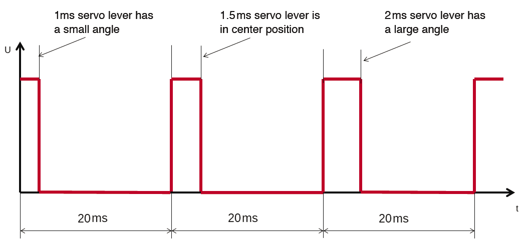
As soon as a servo motor receives a signal, it moves to the matching position at the maximum possible speed and remains there. The servo motors have control electronics that help them do this. Of course, maximum possible speed also means maximum power consumption. Note that it takes quite a lot of power to move servos, which is why it makes sense to decouple the power supply from the microcontroller and motors – otherwise the program could crash. Sometimes the voltage drops so much when a servo is moved quickly that the servo’s control electronics no longer work properly and the position change is completely uncontrolled. The servo then more or less runs wild. You need to make sure that the power supply offers sufficient current at all times.
When installing servos, it is also important to know the position of the lever arm to prevent the servo from damaging the mechanical components. It’s a good idea to use a servo tester to prevent this from happening: It checks the servos for correct function before you install them.
Encoder Motor
The encoder motor is an electric motor with a gearbox that reduces the speed while increasing the torque. The gearbox reduction ratio is 1 to 21.3. There is a pulse generator on the electric motor’s axis. It delivers 63 pulses per revolution of the encoder motor axis. This fairly peculiar value is attributable to the reduction ratio of the gearbox. The number of pulses makes it possible to determine how many revolutions the motor has made. If you extrapolate it, you can even get the distance traveled by the car.
The encoder motor in the kit works with a 9V power supply. I used a 6V power supply for this article, which makes it a little slower, but it still moves the car along well.
To be able to evaluate the signals from the pulse generator, you need to look at it in a little more detail. It works with 9V operating voltage and outputs the pulses via an open collector output. If you connect an output of this type to a digital input in the usual way, you will not get a usable signal: You’ll need an additional external resistor. This raises the question of why open collector technology is used so often if these components cannot be used without additional circuitry. There are actually some good arguments in favor of the technology: The open collector gives you the ability to freely select the external resistor and the operating voltage. This also means that the voltage and the possible current can be freely defined within wide limits. In other words, components with an open collector support very flexible use. Open collector outputs can be found in many semiconductors. All devices that work with I2C use open collector outputs for the bus connections. This means that the I2C bus can be adapted to the number of nodes.
Test Setup
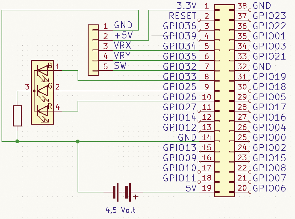
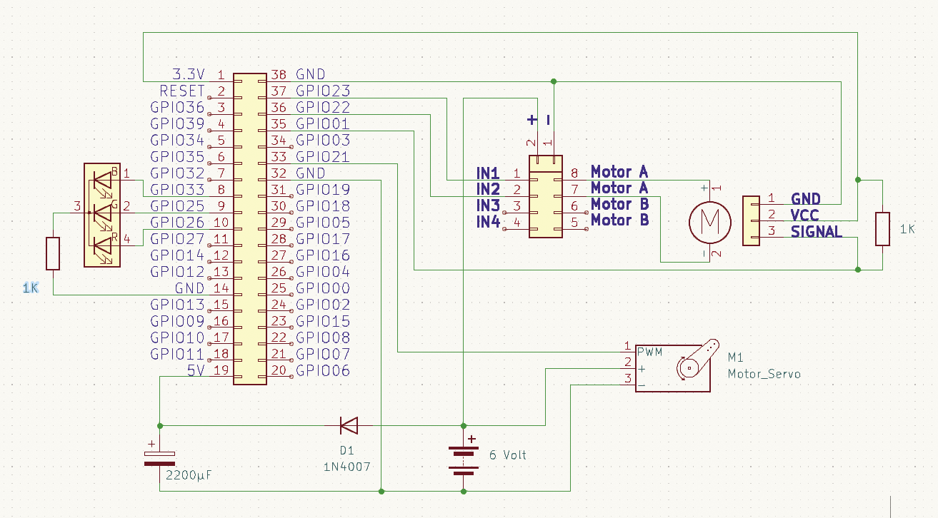
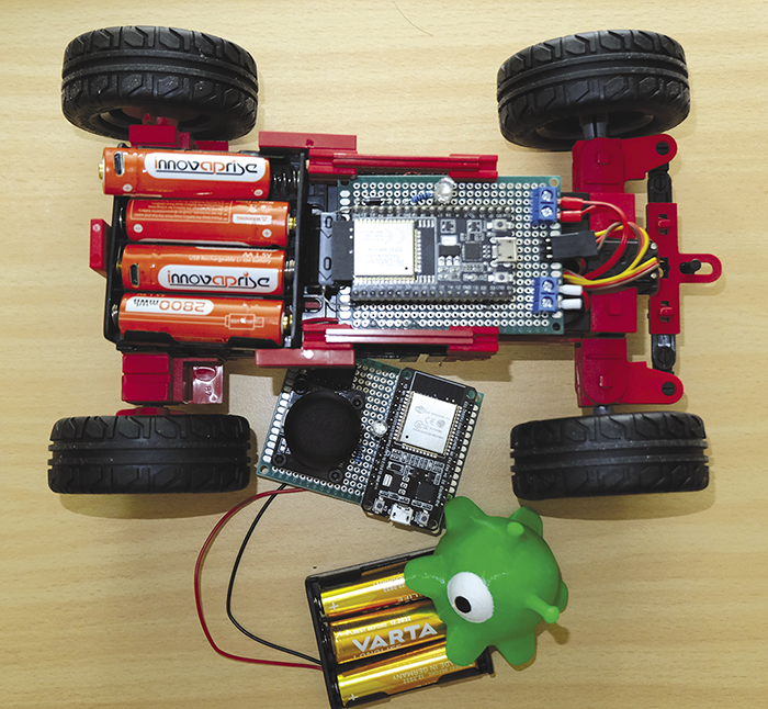
The aim of my project is to steer the car with a simple remote control. I used an ESP32 as the microcontroller. In fact, I needed two of these chips: one for the remote control and one for the receiver. I connected a joystick to the controller in the remote control to steer the car, while the controller in the car controls a motor driver for the drivetrain.
The diode and the relatively large capacitor in the power supply stabilize the supply voltage for the ESP32. The two controllers have RGB LEDs to indicate the current status. You can use the circuit diagrams in Figures 3 and 4 to connect the components; Figure 5 shows the finished car with the remote control.
Test Programs
Each microcontroller requires a separate program. For the vehicle’s program, the first code block (Listing 1) creates an access point on the ESP32 with predefined parameters. Then the PWM outputs for the motors are defined. Variables I1 (line 23) and I2 (line 24) represent the encoder motor’s two rotation directions. The pins on the motor driver are labeled I1 and I2.
Listing 1: car.py
01 import network
02 import socket
03 import time
04 import machine
05 port = 1701
06
07 ap = network.WLAN(network.AP_IF)
08 ap.active(True)
09 ap.config(ssid='FT-CAR')
10 ap.config(password='FT-CAR-Password')
11 ap.config(authmode=network.AUTH_WPA_WPA2_PSK)
12 ap.ifconfig(('192.168.42.42', '255.255.255.0',
13   '192.168.42.42', '192.168.42.42'))
14 while ap.active() == False:
15   print("*",end="")
16   pass
17 print('Connection successful')
18 print(ap.ifconfig())
19 time.sleep(.5)
20
21 servo = machine.PWM(machine.Pin(21))
22 servo.freq(50)
23 I1=machine.PWM(22)
24 I2=machine.PWM(23)
25 I1.freq(8000)
26 I2.freq(8000)
27
28 s=socket.socket(socket.AF_INET, socket.SOCK_DGRAM)
29 s.bind(('192.168.42.42',port))
30 print('waiting...')
31 while True:
32   data,addr=s.recvfrom(1024)
33   print('received:',data,'from',addr)
34   x = int(str(data.split()[0].decode()))
35   y = int(str(data.split()[1].decode()))
36   b = int(str(data.split()[2].decode()))
37   print("X: "+str(x))
38   print("Y: "+str(y))
39   print("B: "+str(b))
40   x=2000000-(x*250)
41   servo.duty_ns(x)
42   if (y > 2148):
43     y = 45000+((y-2048)*10)
44     print ("1:"+str(y))
45     I1.duty_u16(y)
46     I2.duty_u16(0)
47   elif (y < 1948):
48     y = 45000+((2048-y)*10)
49     print ("2:"+str(y))
50     I2.duty_u16(y)
51     I1.duty_u16(0)
52   else:
53     I1.duty_u16(0)
54     I2.duty_u16(0)
The next code block starts a UDP server on port 1701 (Star Trek fans will know why). I use UDP because the data rate is higher and we do not need the error correction that TCP offers. Inside the while loop (line 31), the incoming packets are decoded and the joystick values they contain are converted so as to control the motors in a meaningful way.
At this point, note that the joystick is not very precise and does not fully utilize the full lever travel, but at least it is inexpensive. Finally, the program also contains code that uses the RGB LED’s color to indicate the current status.
Now it’s time to turn to the remote control program (Listing 2). After starting up, the remote control attempts to connect to the vehicle’s access point. If this works, the joystick’s measured values are sent continuously to UDP port 1701. Here too, an RGB LED indicates the current status.
Listing 2: controller.py
01 from machine import ADC,Pin
02 import time
03 import network
04 import socket
05
06 port = 1701
07 serverIp = "192.168.42.42"
08
09 xAxis = ADC(Pin(34, Pin.IN))
10 xAxis.atten(xAxis.ATTN_11DB)
11 yAxis = ADC(Pin(35, Pin.IN))
12 yAxis.atten(yAxis.ATTN_11DB)
13 button = Pin(32, Pin.IN, Pin.PULL_UP)
14
15 wlan = network.WLAN(network.STA_IF)
16 wlan.active(True)
17 wlan.connect('FT-CAR', 'FT-CAR-Password')
18 while(wlan.isconnected() == False):
19   print("*",end="")
20   time.sleep(1)
21   pass
22 ip = wlan.ifconfig()[0]
23 print(ip)
24
25 s=socket.socket(socket.AF_INET, socket.SOCK_DGRAM)
26 while True:
27   xValue = str(xAxis.read())
28   yValue = str(yAxis.read())
29   buttonv = str(button.value())
30   data = str.encode(xValue+" "+yValue+" "+buttonv)
31   time.sleep(0.1)
32   s.sendto(data,(serverIp,port))
The two test programs are only simple examples intended to demonstrate how to set up a granular control system. Sophisticated error handling would do the two programs a world of good, so don’t hesitate to improve the code. To run the programs automatically at startup, you need to convert the file names to main.py. If you want to see the car in action, you will find a video on YouTube.
Conclusions
One thing is certain: After this project, I view all kinds of remote control applications differently. It takes a huge amount of work even to drive a simple car. But, if you persevere, you will have a working basic structure that can easily be extended. You could add indicators, distance warning systems, brake lights, horns, and even autonomous driving, to give just a few examples. I hope you will enjoy experimenting with the Maker Kit Car.


