Feed the Meter
Parking meters and vending machines detect and count the coins you insert, but how do they work? We’ll show you how to mimic the functionality with some particleboard, a Raspberry Pi Pico, a few extra chips, and some Python code.
Counting coins is a problem that was solved decades ago, but I was wondering whether I could come up with a solution of my own. While I may not have the same set of sophisticated tools that a parking meter manufacturer has, it should certainly be possible to create an electronic coin counter using just a Raspberry Pi Pico and some common components. Writing software that can count is trivial, but how do you detect what type of coin was inserted? If you assume that only legal US coins will be used, the easiest way to recognize them is by measuring their diameter. Table 1 lists the diameters of US coins, both in millimeters and in inches.
|
Coin |
Metric |
Imperial |
|
Penny |
19.05mm |
0.75in |
|
Nickel |
21.21mm |
0.835in |
|
Dime |
17.91mm |
0.705in |
|
Quarter |
24.26mm |
0.955in |
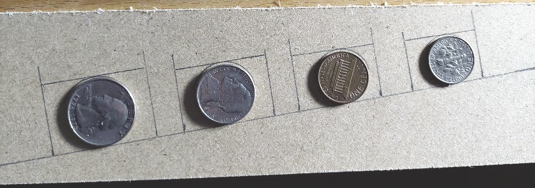
I decided to sort the coins using different sized slots. The coins roll down a small ramp and pass several cut-out slots. If the coin is the correct size, it falls through the slot. The required width of the slot depends on how fast the coin is rolling past whereas the height of the slot needs to be slightly larger than the actual coin while still being smaller than the next largest coin. In my case, the slots were approximately twice the width of the coin (see Figure 1).
It is not difficult to draw a small rectangle, but it is tricky to try and cut it out with straight edges that accurately follow the rectangle. Making a cardboard prototype was no problem, but it took some more effort to cut the slots out of particleboard.
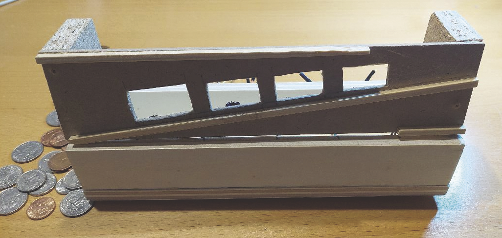
The ramp that the coins roll down needs to be slightly tilted to one side (see Figure 2). This tilt fulfills two functions: First, it ensures that the coin will fall through when it reaches the correct slot. Second, it creates friction that prevents the coin from racing down the ramp at full speed and overshooting the correct coin slot. The ramp has a 10 percent slope, and the entire board is tilted 10 percent. The only problem with this ramp is that it should have had more space above each of the coin slots. I had originally planned to have a small strip of wood across the top. However, because the board was not tall enough, it prevented quarters from fitting through.
Recognizing Coins
This particleboard structure can be used to separate the coins into their individual slots, but it does not count them. Counting requires detecting when a coin falls through a slot. This can be done using a TCRT5000 module which uses an infrared (IR) sensor to sense distance and color. The module includes both an IR transmitter and a receiver. It continuously generates an infrared signal. When an object is present, the signal reflects and the IR receiver detects it. The value is read directly from the pin without needing to use either I2C or SPI. (See the “TCRT5000 Variations” box about two types of TCRT5000 chips.)
During this project, I discovered that there are two different types of the TCRT5000 chip. I have used the module with three pins: power, ground, and data out. The three-pin module returns
1 when the object is detected and 0 when no object is detected.There is also a four-pin module which returns both an analog and a digital value when an object is detected. The four-pin module is often used in line-following robots but can also be used for collision detection.
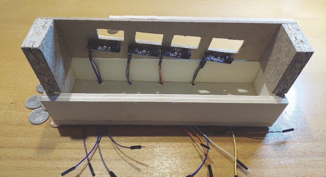
Each coin slot must be fitted with a TCRT5000 module (Figure 3) and the main software loop will check each module to see if it has detected a coin. The TCRT5000 is a very simple device. Unlike other I2C devices, it requires no setup. Simply apply power and read the data pin. The downside is that it has no memory – it is a “dumb” device. The module needs to be polled to detect a coin falling through the slot, and once it has detected a coin, continuous polling must go on until the coin has cleared the detector.
Displaying Amounts
A coin counter is not very useful if it cannot display the amount counted. To output the values of the coins counted I used a four-digit seven-segment display: That is perfect for numbers as it can display up to four digits but it is also possible to add a decimal point to the right of any of the digits.
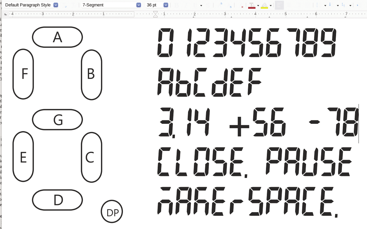
The seven-segment display has this name because it composes each digit of seven individual lines (Figure 4, left) each of which can be turned on or off. Those seven lines are enough to form the digits 0 through 9. If you accept a mixed usage of uppercase and lowercase characters, you can also show hexadecimal digits A through F (Figure 4, right). With clever usage, you can write simple words, such as CLOSE or PAUSE. These displays are common in consumer electronics such as microwaves and DVD players. Some letters need a little creativity, for example it is hard to show an “M” with only seven segments.
There are two common types of seven-segment display. The first one is a sophisticated I2C controlled module. Such a device supports the I2C protocol, a small bit of memory, an address (by which it can be individually referenced), and quite often also a multiplexer chip that controls the display. When you use this kind of module you can simply pass the value you want to display to the module with a specific address. Each display has its own address, so multiple identical displays can be easily controlled.
The second type is simpler: It is made up of the display and a lot of pins to control each segment. There is no controller that translates digits to on/off states of segments. For this project, I’ve used this type of seven-segment display.
The four-digit display that I’ve used is controlled with just twelve pins. Of the first eight pins, each one controls one of the segments as well as the decimal point. The remaining four pins control which of the four digits is active. This is similar to writing to memory with a 4-bit address bus and 8-bit data bus. It is possible to have more than one of the four digits active, but all four digits use the exact same seven inputs. You can display different values across the four digits by activating each digit for a brief amount of time, such as a few milliseconds. If you do this for all of the digits repeatedly, you will see a full four-digit number due to persistence of vision (POV): The eye perceives images for longer than their actual durations. Thus, when you display all the digits really fast, the image will remain on the retina and it will appear to the observer that all digits are on simultaneously. (See the “Electronic Paper Screens” box for an alternative to seven-segment displays.)
Displaying the total amount is the minimum required functionality for a coin counter. I thought it might also be interesting to display coin counts or perhaps display a picture of the coin being processed. Initially, I used a tiny electronic paper screen for showing this information. The reason I did not use it after basic prototyping was the relatively slow refresh rate. Several coins could roll through the counter before the display fully displayed a coin image.
A Few Lines of Python
The initialization of the coin counter (Listing 1) is not very complex even though it consists of a microcontroller, a four-digit seven-segment display, and a custom printed circuit board (PCB):
- Connect the data pin of each of the four TCRT5000s to the Pi Pico. Each device is assigned to a
Pinobject associated with one of the coin slots and given a user-friendly name (lines 7-10). - The 12 pins of the seven-segment display can be grouped roughly into two sets for individual segments (“data bus”) and for digit selection (“address bus”). Each of those is directly assigned to a Pi Pico pin, again using
Pinobjects (lines 13-26), and will be used to directly control segments or digits on the display. - One important step is to initialize all variables to a known state. This is especially true for the pins that are connected to the seven-segment display. This initialization has to take place just once, but it is cleaner to put it into separate functions (lines 29-35).
Listing 1: Initialization of All Devices
01 from time import sleep_ms
02 from machine import Pin
03
04 OnboardLedPin = Pin(25,Pin.OUT)
05
06 # sensors
07 quarters = Pin( 8,Pin.IN)
08 nickels = Pin( 9,Pin.IN)
09 pennies = Pin(10,Pin.IN)
10 dimes = Pin(11,Pin.IN)
11
12 # "address bus": select the digit
13 segment_dollartens = Pin(27,Pin.OUT)
14 segment_dollarone = Pin(26,Pin.OUT)
15 segment_centtens = Pin(22,Pin.OUT)
16 segment_centone = Pin(28,Pin.OUT)
17
18 # "data bus": control a segment
19 segment_dp = Pin(16,Pin.OUT)
20 segment_c = Pin(17,Pin.OUT)
21 segment_g = Pin(18,Pin.OUT)
22 segment_a = Pin(19,Pin.OUT)
23 segment_f = Pin(20,Pin.OUT)
24 segment_b = Pin(21,Pin.OUT)
25 segment_d = Pin(14,Pin.OUT)
26 segment_e = Pin(15,Pin.OUT)
27
28 # initialization
29 def alldigitsoff():
30 segment_dollartens.low()
31 segment_dollarone.low()
32 segment_centtens.low()
33 segment_centone.low()
34
35 def allsegmentsoff():
36 segment_a.high(); segment_b.high()
37 segment_c.high(); segment_d.high()
38 segment_e.high(); segment_f.high()
39 segment_g.high()
A lot of the code for this project is for displaying individual digits on the seven-segment display. Listing 2 contains the draw_6 function, which displays the number 6 by activating segments A, F, G, E, C, and D (in this order). The program contains similar functions for the other numbers, which are not being printed in the article.
Listing 2: Display Number 6
def draw_6():
   segment_a.low()
   segment_f.low()
   segment_g.low()
   segment_e.low()
   segment_c.low()
   segment_d.low()
My particular seven-segment display is a common anode so the segments that make up the digit receive power from the Pi Pico, and the pins that select the digit act as ground, completing the circuit.
The real heart of the coin counter code is the function coincounter, as shown in Listing 3. It runs an infinite loop and continuously checks whether any coins are falling through one of the coin slots. The code is fairly repetitive, as each of the four coins is processed in the same way (lines 8-23). For example, when the function detects a quarter (line 8), it will enter an inner loop for further processing. It takes a short period of time for a coin to fall through the slot past the sensor, thus it is necessary to wait for the currently detected coin to move out of sensor range (line 9). In lines 10 and 11, I increase the number of quarters and the total amount (in cents).
Listing 3: Counting Coins and Calculating the Total
01 def coincounter():
02    quarter_cnt = 0; dime_cnt = 0; nickel_cnt = 0;
03    penny_cnt = 0; total = 0
04
05 i = 1 # loop counter
06 while (i < 300):
07    drawdigits(total)
08    if quarters.value() == 1:
09       while quarters.value() == 1: sleep_ms(1)
10       quarter_cnt = quarter_cnt + 1
11       total = total + 25
12    if dimes.value() == 1:
13       while dimes.value() == 1: sleep_ms(1)
14       dime_cnt = dime_cnt + 1
15       total = total + 10
16    if nickels.value() == 1:
17       while nickels.value() == 1: sleep_ms(1)
18       nickel_cnt = nickel_cnt + 1
19       total = total + 5
20    if pennies.value() == 1:
21       while pennies.value() == 1: sleep_ms(1)
22       penny_cnt = penny_cnt + 1
23       total = total + 1
24
25    if (i % 100 == 0): print(i)
26    # uncomment for limited runs
27    # i = i + 1
At the start of each outer loop, I call the drawdigits function, which then displays the current value of total via the seven-segment display. It splits the total amount counted so far (which is the number of cents) into left and right digits of dollar and cent amounts (lines 5-8 of Listing 4). For example, if total is 123 which corresponds to $1.23, then I need to display 0, 1, 2, 3 from left to right, and I set
dollartens = 0; dollarones = 1
centtens = 2; centones = 3
Listing 4: Updating the Seven-Segment with Totals
01 # get each of the digits, display each one briefly,
02 # do it 20 times.
03 def drawdigits(amount):
04    # get amount digits, right to left
05    centones = amount % 10; amount //= 10
06    centtens = amount % 10; amount //= 10
07    dollarones = amount % 10; amount //= 10
08    dollartens = amount % 10
09
10    showtime = 1
11    for count in range(20):
12       drawsingledigit(centones, segment_centone, showtime, False)
13       drawsingledigit(centtens, segment_centtens, showtime, False)
14       drawsingledigit(dollarones, segment_dollarone, showtime, True)
15       if dollartens > 0:
16          drawsingledigit(dollartens, segment_dollartens, showtime, False)
The rest of the function repeatedly displays each digit in turn (line 12-16). Initially the total amount will not be greater than 999 ($9.99), so the digit for tens of dollars (on the very left) is only shown when we have to (lines 15-16). The function drawsingledigit (Listing 5) will then activate the given digit (for example segment_dollarone) and call the appropriate draw_? function for the value that needs to be displayed (in the example: dollarones).
Listing 5: Drawing a Digit
01 # display a digit for duration milliseconds
02 def drawsingledigit(numberdig, whichdigit, duration):
03     functlist = [draw_0,draw_1,draw_2,draw_3,draw_4,
04        draw_5,draw_6,draw_7,draw_8,draw_9]
05     whichdigit.high() # select the position
06     allsegmentsoff()
07     # select the right draw_? function
08     draw_x = functlist[numberdig]
09     draw_x()
10     time.sleep_ms(duration)
11     whichdigit.low()
Putting It All Together
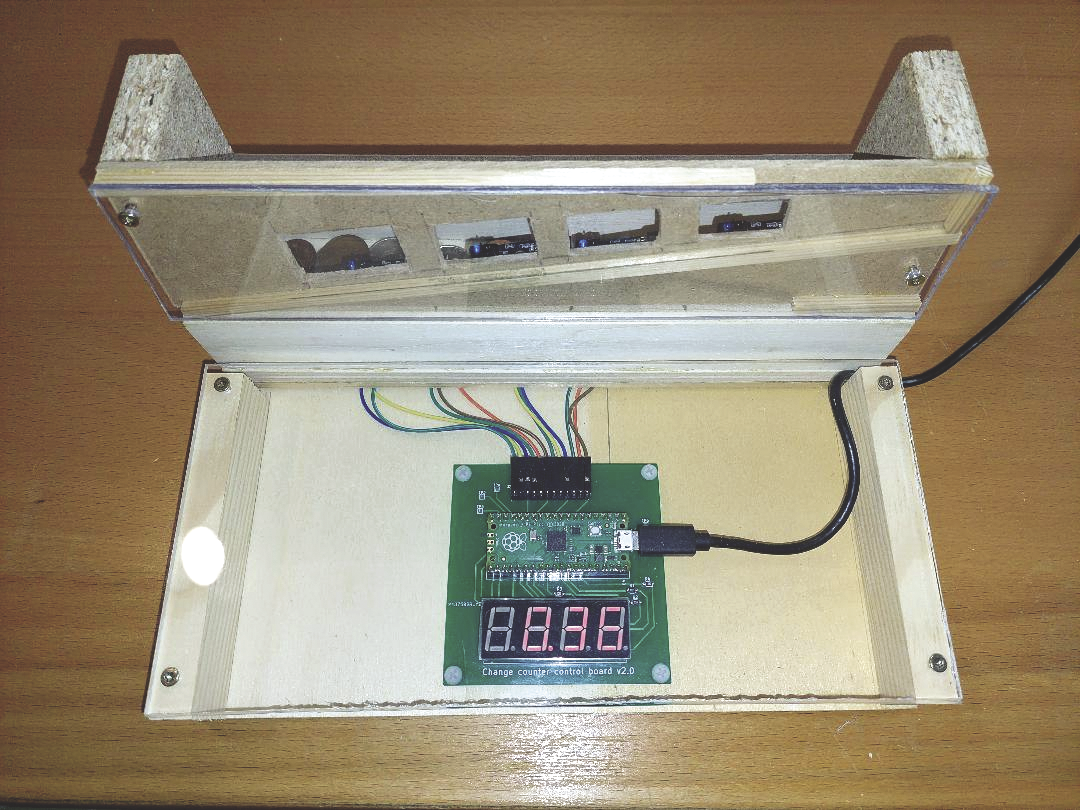
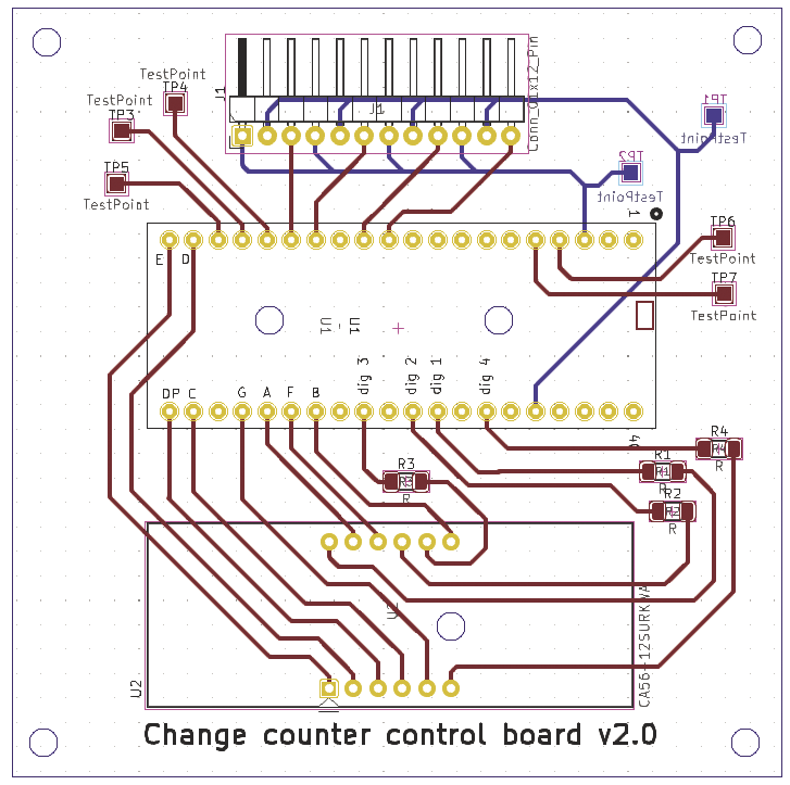
Each of the four TCRT5000 modules needs three connections and the four-digit seven-segment display requires 12 connections to the Pico to control the input and output. Using a microcontroller such as the Raspberry Pico is quite easy in small projects, but due to all of the required connections this would lead to a rats nest of wires that can be difficult to organize or hide. I have designed a small PCB using the open source KiCad electronic design tool. My PCB holds the Pico and the seven-segment display in place, and all TCRT5000 modules can be connected to this board (see Figure 5). This gives a much cleaner look as well as improved reliability because jumper wires don’t always make the best connection on breadboards and can cause some or all of the project to cease working.
Despite taking the greatest of care, the coin counter is not quite perfect. In my tests, about two percent of the coins went down the chute without being counted. This only occurred at the quarter slot, and it seems to be caused by the sensor placement. Coins falls through the chute in slightly different ways depending on the speed they are traveling down the ramp. This makes the placement of the sensor tricky. Old coins can cause problems, as they tend to have deformities or oxidation buildup. This can cause the coin stop before it reaches the correct chute. This problem is most likely caused by using wood: While it does not add too much friction for fresh coins, it does in the case of deformed and dirty coins.
Creating the coin counter (see Figure 6 for the final working model) with these materials was fine for a prototype, but a 3D printer would allow for more precision, which should lead to far more accurate results. Using a 3D printer could reduce any friction and guarantee coin slots that are much closer to the ideal size. This has been a fun project, but it allows a glimpse into why commercial products may create several different prototypes during their design phase. The placement of the various components could be improved. For example, if I were to design a second prototype, I could make the board with the ramp a bit taller so that the coin slot can be the size of a quarter. I am happy with my choice of acrylic glass, as it shows off the inner workings. The goal was to demystify electronics and perhaps inspire my nieces to delve into electronics or software development.
