Nicely Packaged
The official Raspberry Pi 5 case is not the perfect solution for all applications, so it makes perfect sense to design and 3D print your own case.
The Raspberry Pi 5 offers many new functions. Unfortunately, the original case that is sold by the Raspberry Pi Foundation is too small to make full use of all the options. This starts with the GPIO header: The 40-pin plug is very awkward to connect. The lid does not close properly, and it covers the fan. The case itself is so tightly dimensioned that the factory-fitted fan struggles to circulate the air. Things get even more cramped if you use the Active Cooler. Apparently no one considered the fact that the battery for the Real Time Clock (RTC) also needs some space. All in all, a usable case needs to offer more space and offer some openings for cooling. Ideally, it should be large enough to provide space for any Hardware Attached on Top (HAT) you choose to install.
My plan was to develop a case to meet even the toughest requirements; it also had to be sufficiently flexible to cope with future requirements. The “Requirements” box summarizes the design goals and describes how I’ve dealt with some of the problems of the official case. I built the case myself using a 3D printer. To create the model for printing, I used Onshape, an online CAD program that is free for private use. Note that all models created with Onshape are publicly accessible. Video tutorials will help you familiarize yourself with the program.
• Air flow within the housing must be guaranteed. This is why I planned for large ventilation slots with space for the Active Cooler.
• Access to the GPIO header must be possible without restrictions; the cut-outs in the case must be large enough to allow for this.
• The case has to offer enough space to accommodate a HAT. To ensure that the HAT and the cooler do not get in each other’s way, the HAT is mounted vertically in the housing using an angled socket strip.
• The backup battery for the RTC also needs a fixed location.
• The Raspberry Pi 5 has a connection for an external power button that needs to be taken into account.
Model
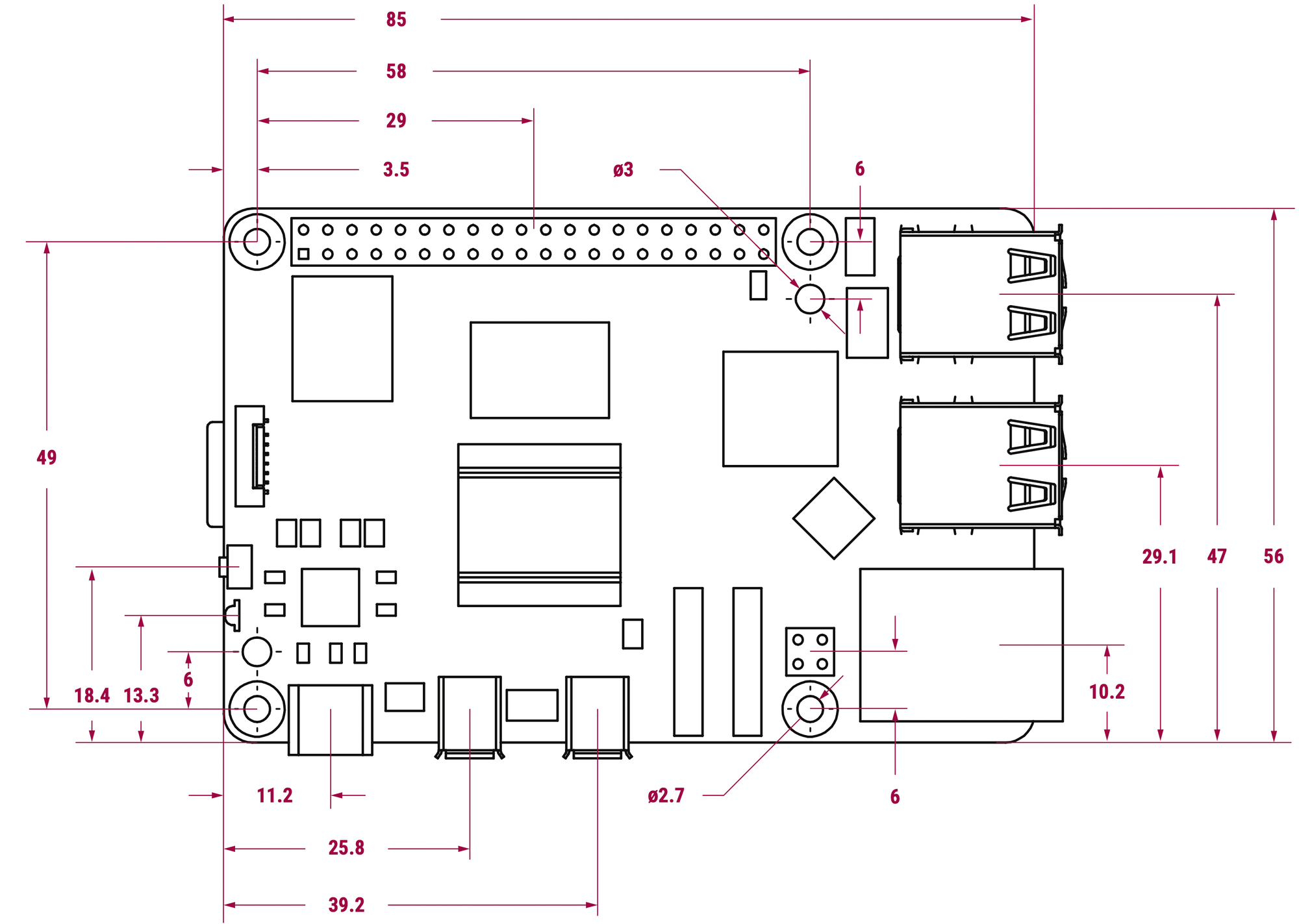
Creating a 3D model is an iterative process that usually requires several attempts until everything fits as desired. Precise measurements are a great help here. Let’s take a look at the data sheet (Figure 1) of the Raspberry Pi 5. We can take some measurements for our case from this, such as the space between the mounting holes. But not all of the required dimensions can be found here; you will need a caliper gauge to determine the others.
Next, it’s time to consider the case’s structure; in principle, it has to consist of a lower and an upper shell. The lower part houses the Raspberry Pi with all the general components such as switches and battery. The upper half can vary depending on the application:
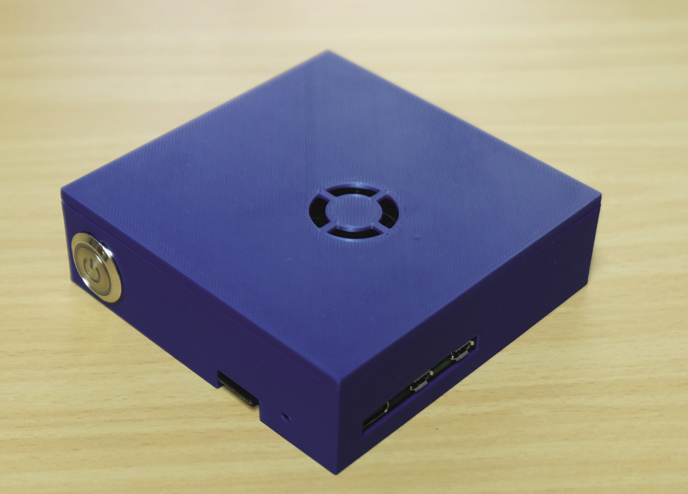
- If you want to use the Raspberry Pi without any components connected to the GPIO, a simple lid is sufficient (Figure 2).
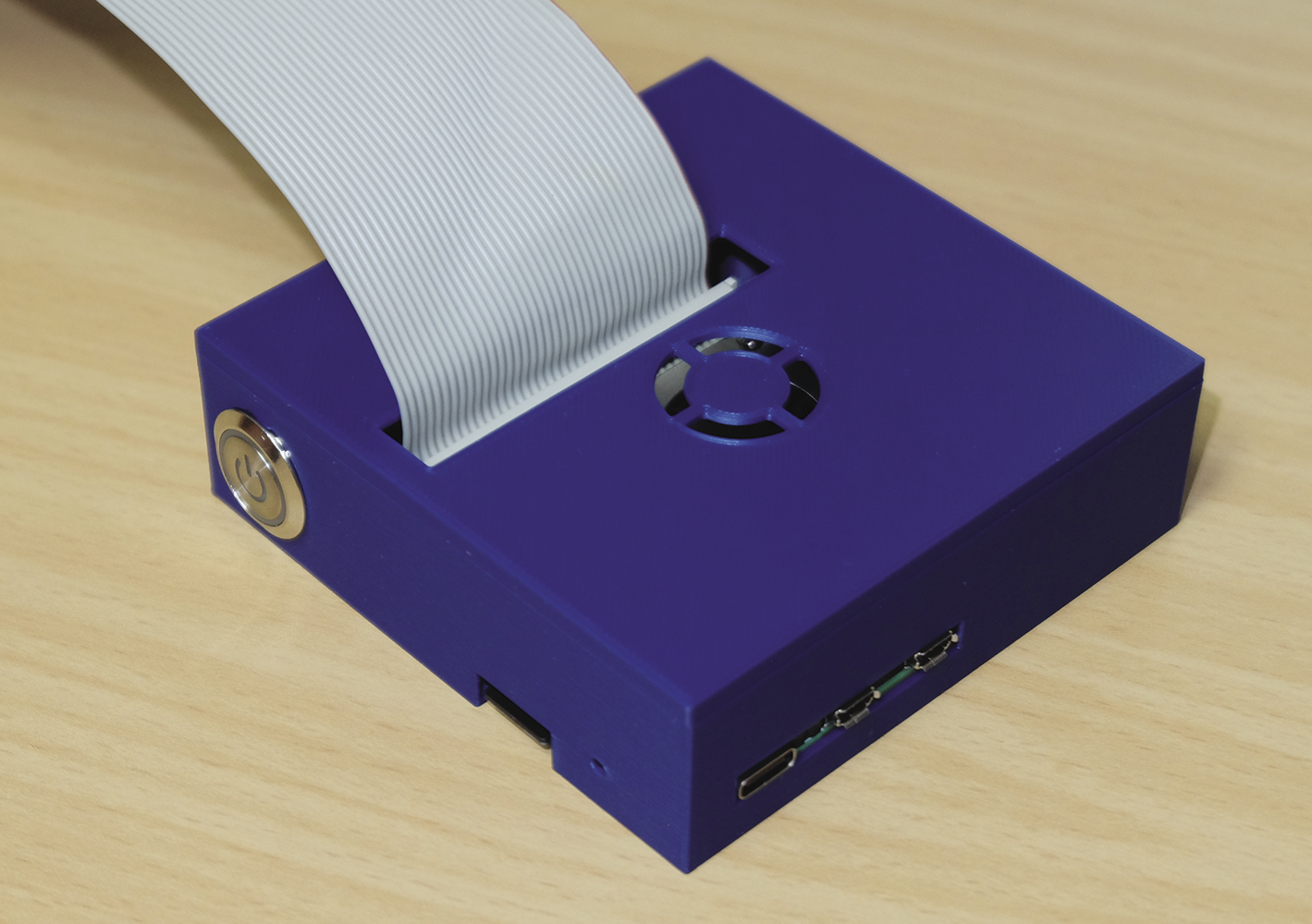
- If instead, you will be using the GPIO, the upper part of the housing needs a cable pass-through (Figure 3).
- And finally, if you want to use a HAT or a separate circuit board on the GPIO, design the cover to be as tall as needed, and add more cutouts if required (Figure 4). As the HAT then occupies the space in which the button is located, it has to move to the upper part of the housing.
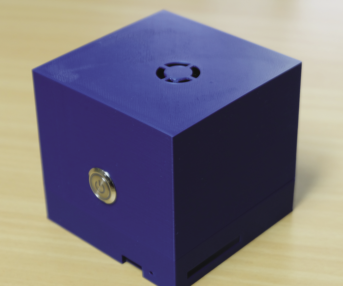
The two shells are designed to fit into each other, and magnets glued in each half hold them together.
There are a few general points to consider when developing models for the 3D printer. It is advisable to provide some space between the housing and the circuit board; 0.5 millimeters will do the trick here. If the gap is too small, you may not be able to remove the circuit board. During the design phase, you also need to make sure that the 3D model matches the layer height of the printer: Otherwise the 3D printout will not have the expected dimensions. Even in the age of CAD, it is extremely useful to create a sketch on paper first. When you mount the Raspberry Pi board in the case, make sure that the case does not press on the built-in power button.
If you have already mounted a heat sink on the Raspberry Pi, heat it up using a hair dryer to loosen the adhesive. The heat sink can then be removed with a gentle twisting motion. To be able to use an external power button, you first need to populate jumper JP2, which is located next to the USB-C socket.
Active Cooler
As already mentioned, the original Raspberry Pi 5 case is a little tight. That’s precisely why I developed a custom case. I wanted to be able to use the Active Cooler without too much tinkering and without the GPIO cable obstructing the airflow. I’ve added an air intake on the top of the case, so the warm exhaust air can escape through the large openings in the connectors.
The opening will probably not have this effect in the tall case shell, but the warm air can escape from the case, which prevents heat building up. Using the Active Cooler offers other advantages in addition to improved cooling: The Raspberry Pi runs very quietly, and the WLAN/Bluetooth chip and the power supply are cooled as well as the CPU.
Outtakes
At this point, I want to share some of the failings in my early design attempts; the causes were mainly minor measuring errors and bad ideas. There were many issues with the holders for the magnets that hold the case half-shells together: They need to be flush with the edge of the case, but must not be flush with the edge of the guide. Getting the various cutouts to fit together perfectly also took several attempts. And there was a particularly annoying mishap related to the push button: Everything fitted together, but I was unable to turn the nut on the button because the gap was one millimeter too small. Failed attempts like this can cost you several hours of printing time before you can continue with the project.
Conclusions
Armed with the right software and a little practice, it’s not that difficult to design a case that is tailored to your requirements. Depending on which HAT you want to use, you may need different cutouts. You are bound to experience a few mishaps, but as we all know, we learn from our mistakes.
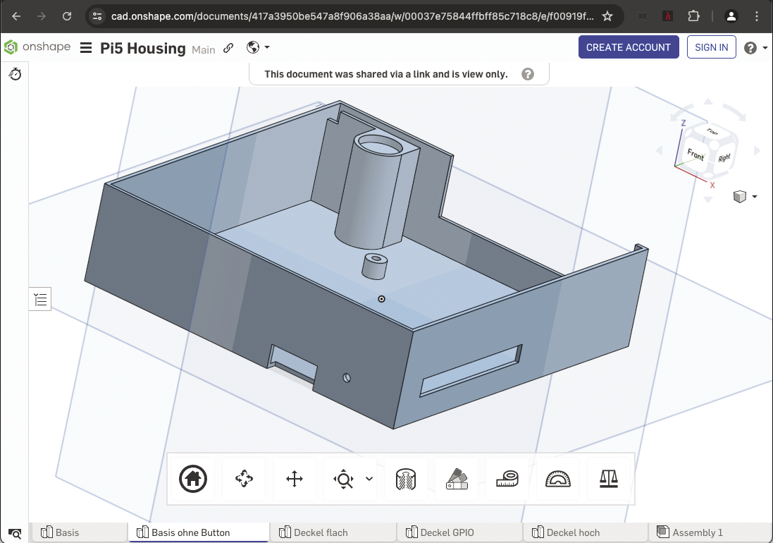
You are welcome to adapt and develop the housing that I’ve developed to your needs; it is available on Onshape (Figure 5). That way, you will gradually arrive at a customized solution that’s perfectly tailored to your needs. I hope you will enjoy the process.
